Calculating Counter Matrix Geometry to Prevent Clay Coating Cracking in Recycled Packaging
Sizing counter matrix channel width to 1.6 times board caliper plus rule thickness prevents clay coating cracking on recycled boxboard by enabling internal delamination.
Channel
A first-off sheet pulled from the die-cutter light table reveals micro-fractures running along the outer primary score. The mineral coating snaps when folded ninety degrees, revealing dark recycled fiber plies underneath. Matrix depth defines strain.
Rule width sets clearance. Board caliper determines depth. Narrow channels split coatings.
Preventing coating rupture on coated recycled board requires precise matching of counter matrix dimensions to board compressibility and coating elongation. Unlike virgin bleached board, recycled folding boxboard contains short, repeatedly processed secondary fibers with lower Z-direction tensile bond strength. When a creasing rule forces the board into the matrix groove, the bottom surface stretches while the internal layers suffer shear delamination.
If the groove geometry restricts internal delamination, tension accumulates entirely on the top clay coating, exceeding its failure strain threshold.
Mathematical Formulation for Recycled Boxboard Sizing
Standard creasing formulas designed for virgin fiber often fail on recycled grades like GD2, GD3, or coated recycled board. Virgin board allows deep internal layer separation, absorbing deformation strain. Recycled board requires wider clearances to achieve an identical folding hinge effect without surface fracturing.
Calculating the correct matrix groove width relies on board caliper, scoring rule thickness, and a material correction factor. The standard calculation reads as follows:
W = t_r + (k_1 t_b)
In this equation, W represents matrix channel width in millimeters, t_r represents creasing rule thickness in millimeters, t_b represents board caliper in millimeters, and k_1 represents the substrate multiplication constant. For virgin solid bleached board, k_1 ranges from 1.4 to 1.5. For clay-coated recycled grades, k_1 increases to a range between 1.6 and 1.8.
This wider dimension accommodates the compressed displacement of lower-pulp plies without over-stretching the stiff mineral coating layer.
A matrix channel width ratio of 1.6 times board caliper plus rule thickness reduces coating tensile strain below 1.2 percent at standard room conditioning.
Matrix groove depth calculation uses board thickness modified by ply density and moisture level. The equation follows:
D = k_2 t_b
Here, D represents matrix channel depth in millimeters, and k_2 represents the depth coefficient. While virgin board utilizes a k_2 factor of 1.0, recycled boxboard requires a reduced factor between 0.85 and 0.95. Compressing recycled board plies too deeply during initial scoring damages the back-ply fibers, leading to crack propagation through to the top coating during final box erecting.
| Board Caliper (mm) | Grammage (g/m²) | Rule Thickness (pt / mm) | Target Depth (mm) | Target Width (mm) | Strain Reduction (%) |
|---|---|---|---|---|---|
| 0.35 | 280 | 1.5 pt / 0.53 mm | 0.30 | 1.10 | 14.2 |
| 0.40 | 315 | 2.0 pt / 0.71 mm | 0.35 | 1.35 | 16.8 |
| 0.45 | 350 | 2.0 pt / 0.71 mm | 0.40 | 1.45 | 18.5 |
| 0.50 | 390 | 2.0 pt / 0.71 mm | 0.45 | 1.55 | 21.0 |
| 0.60 | 450 | 3.0 pt / 1.05 mm | 0.52 | 2.05 | 23.4 |
Incorrect matrix channel dimensions yield severe production failures. Selecting a channel width two tenths of a millimeter too tight forces outer mineral coatings to exceed their ultimate tensile strain limit, tearing open along every primary fold and generating unreadable barcodes, unsealable glue flaps, and immediate rejection of finished packaging lots at customer distribution nodes.

Substrate
Raw fiber structures dictates how surface minerals handle bending forces. Clay coatings lack fiber length. Thick coatings crack easily.
Binder content controls elongation. Fibers separate under shear.
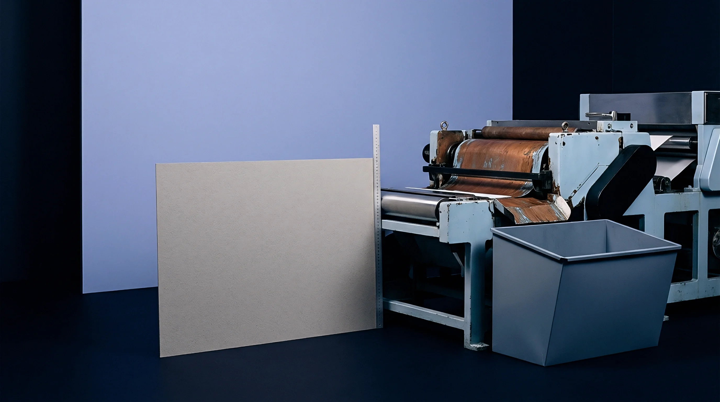
Clay coatings applied to recycled cartonboard consist primarily of inorganic mineral pigments such as kaolin clay and ground calcium carbonate, held together by synthetic latex binders like styrene-butadiene or styrene-acrylic emulsions. The mineral pigment provides brightness and print smoothness, but lacks inherent elasticity. The latex binder introduces flexibility, yet economic considerations in recycled board manufacturing often keep binder concentrations at minimal functional thresholds.
When the underlying paperboard is creased, the top coating undergoes severe local tensile elongation.
Mechanical Constraints in Recycled Fiber Layers
Recycled pulp contains a high proportion of degraded, shortened wood fibers and fine particles. These shorter fibers alter the internal mechanical response during creasing.
In a high-grade virgin board, creasing creates distinct delamination planes between plies. These planes allow individual layers to slide past one another, forming an internal bead that relieves tension on the outer surface. Recycled boards possess uneven density profiles and weaker inter-ply bond strength, causing unpredictable shear failure during deformation.
- Coating Tensile Fracturing occurs when localized outer layer stretching exceeds the elastic elongation boundary of the pigment binder matrix, causing clean line ruptures along the fold crown.
- Inter-Ply Delamination Failure happens when weak core layers collapse unevenly under creasing rule pressure, creating localized stress concentration spots on the top surface.
- Inverted Bead Bulging develops when matrix grooves are sized too deep, forcing the internal shear bead to burst through the back surface rather than folding cleanly inward.
- Shear Plane Shear Banding results from non-uniform fiber alignment in recycled furnish, leading to crooked, irregular creasing lines that cause panel warping on automatic cartoning lines.
Higher latex binder ratios in clay coatings absorb outer bend strain without requiring wider creasing matrix channels.
Mill technical representatives often attribute surface line cracking to atmospheric humidity changes during transit or unexpected variations in secondary fiber elasticity across production lots.
Tooling
Die-cutting components must be configured to accommodate variable board density. Steel counter plates eliminate flex. Phenolic counter plates last.
Moisture restores board ductility.
Selection of counter matrix substrate material directly impacts scoring line precision over long press runs. Pressboard matrix strips provide quick make-ready setups for short runs, but suffer dimensional degradation under repetitive high-pressure impressions. Phenolic resin counters maintain crisp, unyielding channel shoulders across hundreds of thousands of impressions, preserving exact channel geometry across the entire shift.

What Matrix Depth Formula Fits High Coat Weight Recycled Board?
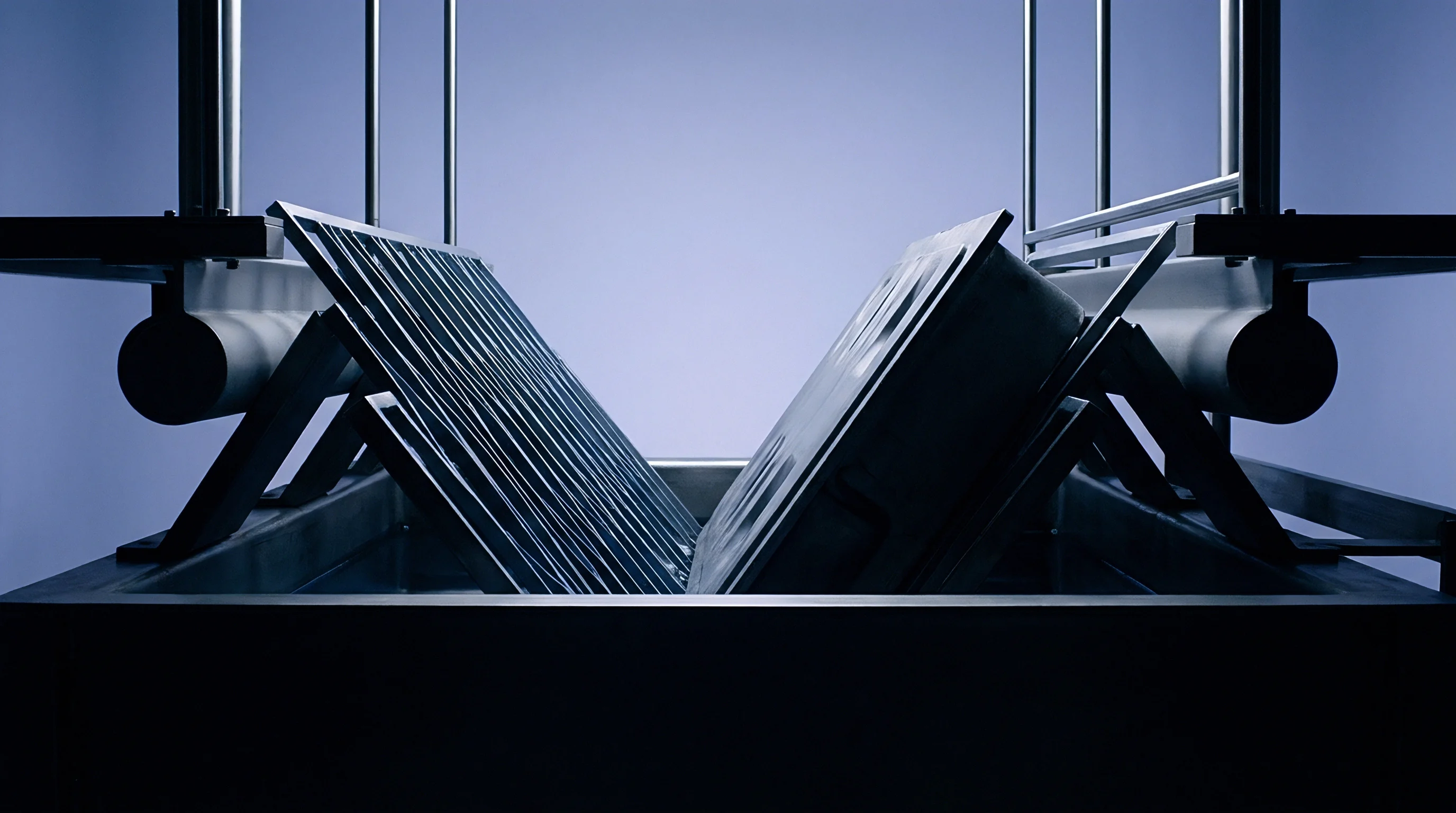
High coat weight recycled boards carrying over twenty grams per square meter of pigment require specialized channel profile geometry to prevent outer coat shearing. Standard flat-bottom grooves create sharp pressure peaks at the channel shoulder, cutting directly into the brittle coat layer. Machining a chamfered shoulder angle between thirty and forty-five degrees redistributes this peak stress across a broader surface area, preserving coating continuity.
- Clean the steel cutting plate using solvent to eliminate residual oil and adhesive deposits.
- Mount the creasing rule with rounded nose contours, verifying radius dimensions with a optical gauge.
- Snap the precision-milled phenolic matrix channel strips onto the corresponding creasing rules across the die.
- Peel off the protective adhesive backing paper from the undersides of the matrix channels.
- Inching the die-cutting platen forward to top dead center transfers the matrix channels onto the counter plate under full operational tonnage.
- Remove the plastic locator jackets smoothly to reveal clean, perfectly aligned groove channels.
- Measure channel alignment using a depth micrometer at five positions across the sheet layout.
Choosing a rule nose radius equal to board caliper prevents sharp line cutting while maintaining low folding resistance.
Verification
Standardized measurement methods isolate creasing defects prior to full production runs. Testing evaluates crease stiffness, surface cracking indices, and internal bead symmetry under controlled environmental conditions. Testing must conform to ISO 187 conditioning standards, keeping samples at twenty-three degrees Celsius and fifty percent relative humidity for twenty-four hours before physical testing.

Quantitative Crease Stiffness and Bending Evaluation
Evaluating creasing performance requires comparing the force needed to fold a scored board sample ninety degrees against the force needed to bend an uncreased sample of the same material. The ratio between these two measurements defines the crease stiffness reduction factor:
C_r = (F_c / F_u) 100
In this equation, C_r is the crease stiffness percentage, F_c is the bending force of the creased sample in millinewtons, and F_u is the bending force of the uncreased sample in millinewtons. An optimal crease on coated recycled board achieves a C_r value between 40 and 50 percent. Values above 60 percent indicate under-creasing, forcing excessive bend strain onto the clay coating.
Values below 30 percent indicate severe internal layer breakdown, risking box corner crushing strength.
Consider a practical testing sequence evaluated on 0.45 mm GD2 recycled board carrying 28 g/m² clay coating. The evaluation compares three counter matrix channel widths using a standard 2.0 pt (0.71 mm) creasing rule:
Under Case A, a tight channel width of 1.25 mm yields a crease stiffness factor of 62 percent. Microscopic inspection shows continuous micro-fracturing along the entire length of the fold line, as outer coating strain reached 2.1 percent. Under Case B, a nominal channel width of 1.45 mm yields a crease stiffness factor of 44 percent.
Outer strain drops to 1.1 percent, displaying zero visible coating cracks under ten-times magnification. Under Case C, an oversized channel width of 1.75 mm reduces crease stiffness to 31 percent. However, the wide channel allows the fold position to wander, creating a irregular crease bead and uneven carton panel dimensions.
| Test Case | Matrix Width (mm) | Matrix Depth (mm) | Crease Force F_c (mN) | Stiffness Ratio C_r (%) | Visual Crack Rating |
|---|---|---|---|---|---|
| Case A (Tight) | 1.25 | 0.40 | 310 | 62 | Grade 4 (Severe Rupture) |
| Case B (Optimal) | 1.45 | 0.40 | 220 | 44 | Grade 1 (No Cracking) |
| Case C (Wide) | 1.75 | 0.40 | 155 | 31 | Grade 2 (Minor Wandering) |
Microscopic evaluation of cross-sectional cuts reveals whether internal delamination planes developed correctly. A clean score line shows three to four distinct delamination fissures inside the core recycled plies, with the outer clay coating maintaining a continuous smooth curve around the exterior bend radius.
- Crease Stiffness Ratio Target sets the acceptable folding force window between forty and fifty percent of uncreased board stiffness.
- Coating Tensile Strain Limit specifies maximum permissible elongation on outer mineral layers to prevent micro-fracturing during ninety-degree folding.
- Delamination Shear Depth defines the required vertical penetration of internal layer separation fissures within the recycled core plies.
- Internal Bead Width Allowance measures the maximum sideways expansion of the folded core bulge to ensure proper glue flap clearing.
Compliance with DIN 55437 score quality rating grade one limits surface clay micro-fracturing to less than five hundred micrometers in length per linear meter of fold.
Adhering to ISO 2493 stiffness testing specifications mandates that crease resistance measurements taken twenty-four hours post-converting supersede any preliminary values recorded immediately off the die-cutter press.
Economics
Scrap generation on high-speed packaging lines directly impacts converter profitability. Cracks ruin barrier function. Defects increase scrap rate.
Make-ready accuracy preserves margin.
Clay coating cracking generates financial losses across multiple stages of product conversion and end-use filling operations. When mineral coatings rupture on high-speed cartoning equipment running at six hundred packs per minute, exposed recycled fibers absorb ambient moisture, softening carton corners and causing machine jams. A single press stoppage on an automated filling line costs thousands of dollars per hour in direct downtime, wasted product, and secondary sorting labor.
Unintended coating micro-fractures compromise moisture barrier properties long before visual clay flaking triggers job rejection on automated packaging lines.
Investing in precision phenolic counter matrix plates adds initial tooling expense during make-ready stages, yet eliminates catastrophic lot rejections. High-precision tooling costs roughly three times more than hand-cut counter channels, but amortizes across run lengths exceeding fifty thousand sheets. The resulting reduction in setup waste, combined with total elimination of cracking defects, yields a measurable return on investment within the first two hours of continuous operation.
How do seasonal temperature shifts in unheated warehouse spaces alter the micro-viscoelastic stability of clay coatings on stored recycled board rolls?