Creasing Matrix Channel Width Calculation Basics for Standard Paperboard Grades
Calculate creasing matrix channel width using the formula W = T + (F × C), selecting factor F between 1.4 and 1.7 based on board grade and fiber stiffness.


Clearance
A two-point steel creasing rule stamps down with twelve tonnes of platen force into a four-hundred-micron folding boxboard sheet. The die platen closes. That downward stroke pushes the board into a precise groove cut into a counterplate or adhesive matrix locator.
When that female groove holds the correct dimensions, the paperboard structure delaminates internally without cracking its mineral-coated outer surface. The paperboard forms a defined internal bead that acts as an engineered mechanical hinge during high-speed folding and gluing.

Standard Calculation Mechanics
Determining the correct channel width relies on a core arithmetic formula used across carton converting lines. Channel width equals the creasing rule thickness plus a specific multiplier of the paperboard thickness. Converting technicians express this relationship as W = T + (F × C), where W designates the channel width, T represents the creasing rule thickness, C represents the measured board caliper, and F represents the material clearance factor.
The rule thickness fixes the baseline.
The material clearance factor accounts for the volume of compressed fiber displaced into the matrix groove when the steel rule seats at bottom dead center. For virgin fiber folding boxboard, European and North American converting operations apply a standard factor between 1.4 and 1.5. Solid bleached sulfate grades, possessing greater sheet density and higher tensile stiffness, operate reliably with a factor of 1.5.
When converting unbleached kraft boards or heavily recycled grades such as white lined chipboard, technicians expand the clearance factor to 1.6 or 1.7. These board compositions require additional lateral clearance to accommodate stiff outer plies and short, brittle recycled fibers.
A wider creasing channel softens folding resistance while a narrower groove risks rupturing the surface liner during automated carton erection.
Channel depth follows a simpler, parallel calculation. Groove depth typically equals the nominal board thickness, expressed as D = C. On rigid bleached virgin boards, some tooling technicians reduce matrix depth by ten percent to increase crease definition on ninety-degree folds. On recycled chipboard, maintaining depth exactly equal to caliper prevents shearing the backliner against the matrix shoulder.
When the die platen strikes, the steel creasing rule forces the board to shear internally across its plies, forming an intact rolling bead along the underside of the carton blank.
Proper matrix sizing preserves the aesthetic finish of printed, varnished, or laminated board packaging. An undersized channel pinches the substrate, cracking the top clay coating or fracturing any applied cold foil along the fold line. An oversized channel creates an ill-defined bead, leading to wandering crease lines, skewed cartons, and excessive fold torque on automated filling machines.
Tooling geometry determines carton squareness long before a pallet reaches the packhouse.


Caliper
Substrate thickness dictates every mechanical clearance variable across the platen die. Board mills measure thickness in microns across metric markets and in points across North American supply chains, where one point equals one-thousandth of an inch. A twenty-point board translates to approximately five hundred and eight microns.
Tooling makers select steel creasing rules based on this substrate dimension to ensure that the rule penetrates the sheet without severing the surface fibers.

Substrate Density across Standard Grades
Paperboard behavior during matrix indentation varies by fiber composition, internal ply structure, and sheet finishing treatments. Chemical pulp plies withstand sharp internal shear, whereas mechanical and secondary recycled fibers crush easily under concentrated vertical loads. Virgin chemical fibers bend smoothly.
- Solid bleached board consists of multiple plies of bleached chemical pulp, delivering uniform density and superior bending resistance without ply splitting.
- Folding boxboard pairs chemical pulp outer layers with a mechanical wood pulp core, providing high bulk and stiffness at lower sheet grammages.
- White lined chipboard incorporates secondary recovered paper fibers in its filler plies, showing reduced ply bond strength and greater sensitivity to matrix pinching.
- Solid unbleached board uses virgin unbleached kraft fibers, offering exceptional tear strength and puncture resistance for heavy retail packaging.
The DIN 55437 test standard evaluates crease formation under laboratory conditions at 23°C and 50% relative humidity. The standard 1.5 multiplier for virgin folding boxboard rests on continuous lab data established at these controlled atmospheric conditions. Lowering plant humidity below 40% dries the sheet, reducing internal fiber elasticity and forcing the line operator to widen the channel multiplier to 1.7 to prevent top-liner rupture.
Caliper drift breaks the fit.
Under DIN 55437 test atmospheres of 23°C and 50% relative humidity, virgin folding boxboard maintains consistent crease recovery when channel width equals rule thickness plus 1.5 times sheet caliper.

Which Board Caliper Governs Channel Clearance?
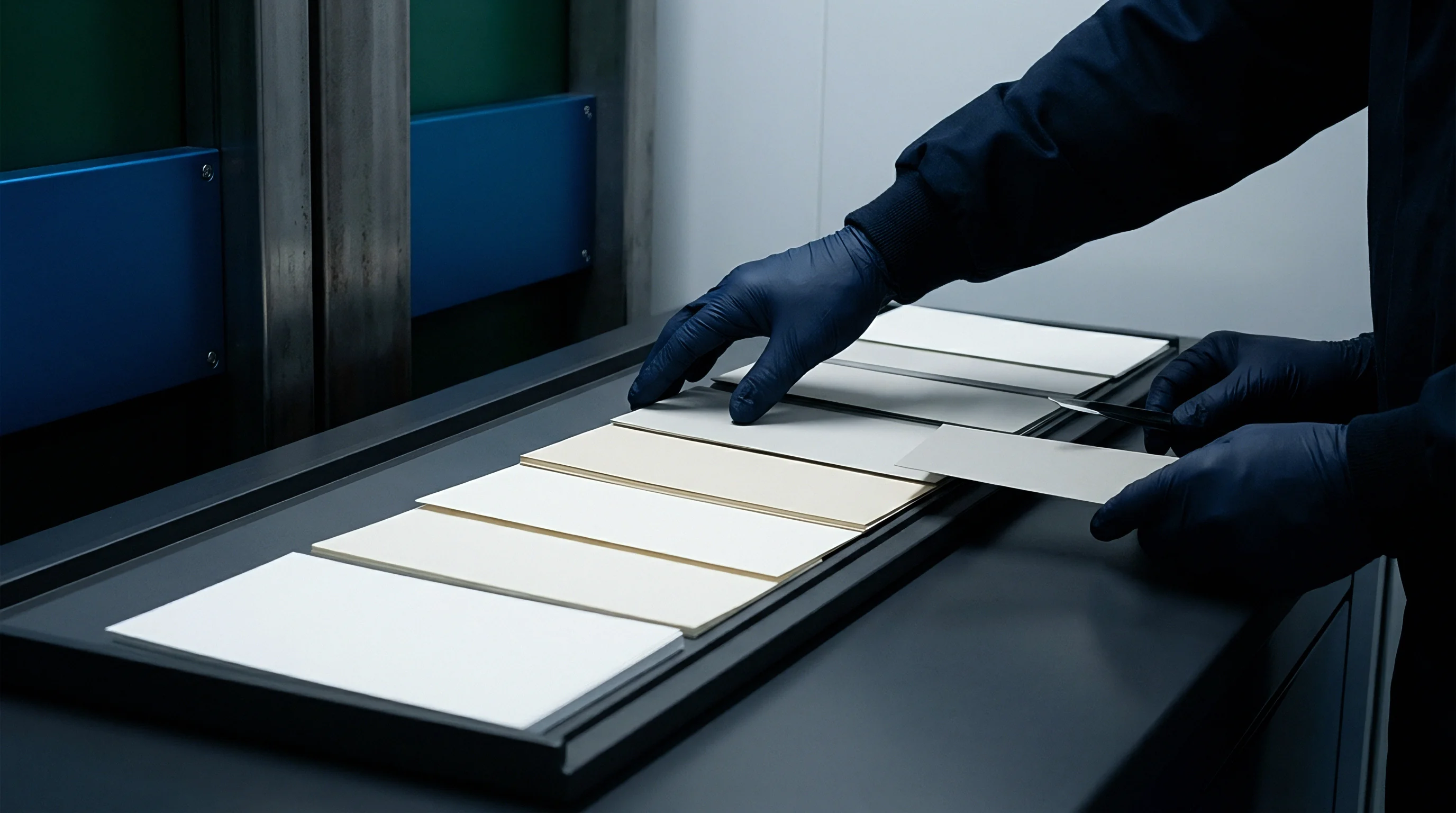
Coated cartonboards exhibit thickness variations between mill production batches. An incoming paperboard lot specified at 450 microns often swings between 435 and 465 microns across mill reels. Tooling technicians base their channel width calculations on the maximum measured caliper of the delivered batch rather than the nominal mill sheet rating.
Measuring the sheet with a micrometer under standard TAPPI T 411 dead-weight conditions prevents underestimating the displaced fiber volume.
| Board Grade | Nominal Caliper (mm) | Rule Thickness (pt / mm) | Clearance Factor (F) | Channel Width (mm) | Channel Depth (mm) |
|---|---|---|---|---|---|
| Solid Bleached Board (SBB) | 0.35 | 2 pt (0.71 mm) | 1.5 | 1.24 | 0.35 |
| Folding Boxboard (FBB) | 0.40 | 2 pt (0.71 mm) | 1.4 | 1.27 | 0.40 |
| Folding Boxboard (FBB) | 0.55 | 2 pt (0.71 mm) | 1.5 | 1.54 | 0.55 |
| White Lined Chipboard (WLC) | 0.45 | 2 pt (0.71 mm) | 1.7 | 1.48 | 0.45 |
| White Lined Chipboard (WLC) | 0.60 | 3 pt (1.05 mm) | 1.7 | 2.07 | 0.60 |
| Solid Unbleached Board (SUB) | 0.50 | 2 pt (0.71 mm) | 1.6 | 1.51 | 0.50 |
Mill technical sheets frequently claim that a general-purpose 1.5 multiplier functions across every production shift, yet converter make-ready crews discover that batch-to-batch moisture loss during warehouse staging stiffens the sheet and causes outer liner splitting under that catalog recommendation.


Channel
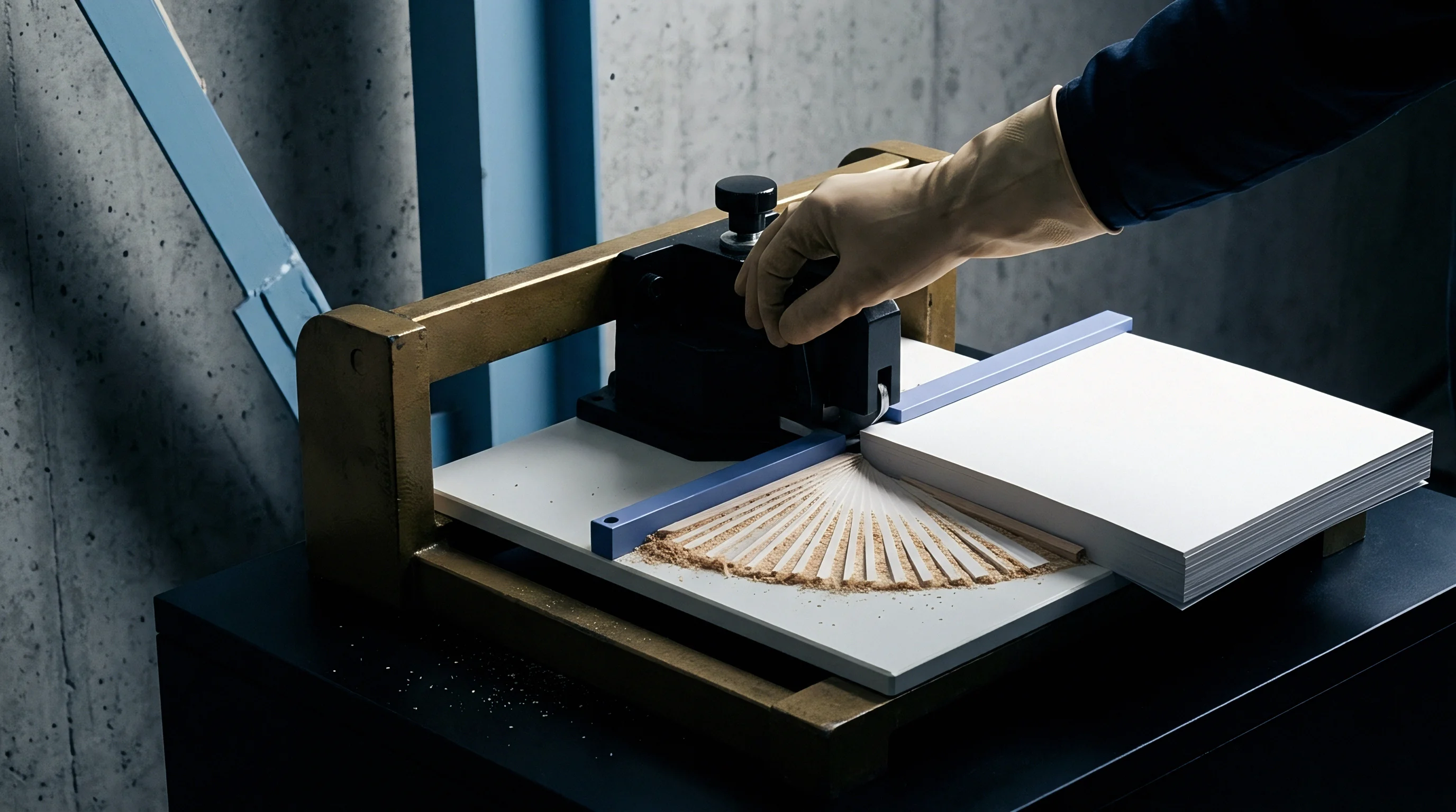
Tooling plates seat the female counter-channel opposite the steel creasing rule. Converting shops select between pressboard counterplates, phenolic resin counters like Pertinax, and self-adhesive creasing matrix strips bonded directly to a steel cutting plate. Each material system offers distinct mechanical tolerances during volume runs.
Adhesive matrix strips feature plastic or composite guide shoulders mounted on a thin steel or film base, allowing rapid changeovers on short carton orders.

Worked Dimensional Sizing Scenarios
Assessing matrix dimensions requires walking through exact converting scenarios with stated parameters. Take a folding boxboard carton specified at 0.45 mm caliper running on a flatbed autoplaten die-cutter. The tooling design specifies a standard two-point steel creasing rule with a finished width of 0.71 mm.
Applying the virgin board factor of 1.5, the calculation proceeds: W = 0.71 + (1.5 × 0.45). The displaced fiber calculation yields 0.675 mm, producing a target channel width of 1.385 mm. Matrix manufacturers offer commercial profiles in discrete 0.1 mm increments, so the technician rounds to a commercial matrix size of 1.40 mm width and 0.45 mm depth.
Now stress that identical job by substituting a recycled white lined chipboard of identical 0.45 mm caliper. Because recycled plies possess shorter cellulose fibers and lower internal delamination resistance, applying a 1.40 mm channel crushes the backliner. Recycled plies delaminate unevenly.
The technician recalculates using a clearance factor of 1.7: W = 0.71 + (1.7 × 0.45), producing a channel width of 1.475 mm. The operator selects a 1.50 mm width matrix with a 0.45 mm depth. That additional 0.10 mm of lateral clearance prevents the outer liner from fracturing when folded 180 degrees on the packaging line.
Similar dynamic clearance calculations govern metal stamping dies in automotive body plants, where sheet ductility dictates die shoulder radii to prevent localized necking. Die-cutting platen tooling applies identical mechanical laws to cellulose fiber bundles.
Precision-milled counterplates maintain exact channel edges over hundreds of thousands of impressions while adhesive strips experience gradual shoulder deformation.

Counterplate Tooling Longevity
High-volume carton runs warrant dedicated counterplates rather than adhesive strips. Milled phenolic counters maintain sharp groove edges across long production runs, holding dimensional register within five microns across thousands of sheets. The choice between adhesive strips and milled counters influences running waste and unit tooling costs.
- Adhesive matrix strips allow rapid manual make-ready on short runs, but adhesive migration and shoulder deformation limit structural stability past fifty thousand impressions.
- Milled Pertinax plates deliver rigid groove geometry across half a million impressions, ensuring precise carton fold angles on high-speed consumer goods packing lines.
- Steel counterplates eliminate groove wear entirely on multi-million run pharmaceutical sleeves, requiring precise laser calibration to avoid tooling clashes.
| Matrix Construction | Channel Width Tolerance (mm) | Wear Limit (Impressions) | Make-Ready Time (Minutes) | Relative Unit Cost |
|---|---|---|---|---|
| Plastic Matrix Strips | ±0.05 | 25,000 | 15 | Low |
| Fiber Composite Strips | ±0.04 | 60,000 | 15 | Moderate |
| Phenolic Counterplate (Pertinax) | ±0.02 | 500,000 | 45 | High |
| Milled Steel Plate | ±0.01 | 2,000,000 | 90 | Very High |
A specific tooling convention establishes that two-point creasing rules of 0.71 mm thickness handle all standard cartonboards up to 0.60 mm caliper; exceeding 0.65 mm caliper forces the toolmaker to install a three-point 1.05 mm rule to eliminate localized pinch tears along the hinge edge. Narrow channels burst the backliner. Tooling errors multiply across shifts.
Selecting an incorrect matrix width forces carton packers to scrap entire pallets because unyielding, stiff score lines jam carton magazines on automatic packaging machinery.

Hinge
Creasing acts as an internal delamination process that transforms a rigid flat board into a functioning double hinge. When the platen press descends, the creasing rule acts as a male punch, pushing the board plies downward into the counter-channel. The outer liner stretches into tension, the inner plies shear along their interfaces, and the back surface bulges outward to form an unbroken bead.
The channel sets the hinge.

Fiber Delamination across Grain Directions
Cellulose fibers align predominantly parallel to the running direction of the paper machine during sheet forming. Bending the board parallel to this grain direction requires different matrix clearance than bending across the grain. Across the sheet grain, stiff fiber bundles resist stretching, requiring the creasing rule to displace more internal fiber volume to prevent face cracking.
Tough kraft liners resist deformation.
When creasing across the grain, technicians widen the matrix channel by 0.1 mm or increase the clearance factor by 0.1 to give the cross-directional fibers room to roll. Creasing with the grain allows a slightly tighter channel, creating a sharp, crisp fold without surface disruption. Crease depth equals board caliper.
Wide channels cause rollover creases.

Do Coating Cracks Trace to Inadequate Width?
Surface checking and clay-coat fractures frequently puzzle packaging buyers after die-cutting. Mineral pigment coatings, decorative lacquers, and metallic hot-stamping foils possess substantially lower elongation limits than virgin cellulose fibers. When a narrow matrix pinches the board, tensile strain concentrates across the outer coating layer, causing immediate hairline fractures along the external crease ridge.
A contract clause mandating zero visible liner rupture at a ninety-degree bend under ten-times magnification forces converters to verify crease channel clearance on every production reel.
Visual inspection of folded carton samples identifies several distinct physical creasing defects resulting from incorrect counterplate channel sizing:
- Liner splitting appears as jagged fractures along the printed exterior fold line, caused by an undersized matrix channel that overstretches outer surface fibers.
- Backside shearing displays continuous parallel cuts along the internal bead base, indicating excessive penetration depth or sharp matrix shoulder edges.
- Rollover creases produce asymmetrical, leaning beads that cause cartons to fold out of square, caused by an excessively wide counter-groove.
- Coating flaking sheds microscopic pigment particles along score lines during automated carton erection, stemming from inadequate internal ply separation.
White lined chipboard crease recovery ratios show a contested variance, where mill technical sheets state a channel factor of 1.6 while high-speed converting floors report cracking unless 1.75 is applied; under this uncertainty, the buyer specifies trial counterplates with graduated widths in 0.05 mm increments before releasing volume cutting dies. Whether incoming moisture variations across seasonal delivery cycles shift the required matrix width sufficiently to warrant dual-die tooling investments remains an open technical debate among folding boxboard converters.

Allowance
Die-cutting calculations directly govern commercial run profitability and line speeds. Carton packaging plants calculate gross line efficiency based on folder-gluer downtime, make-ready duration, and sheet waste percentages. Inaccurate channel dimensions generate high reject rates long after sheets leave the die-cutting press.
Carton gluing lines stop instantly. An unyielding crease increases the bending moment required to fold a carton flap, causing cartons to bow or misfeed inside automated packaging equipment.

Machine Downtime and Folder Gluer Jamming
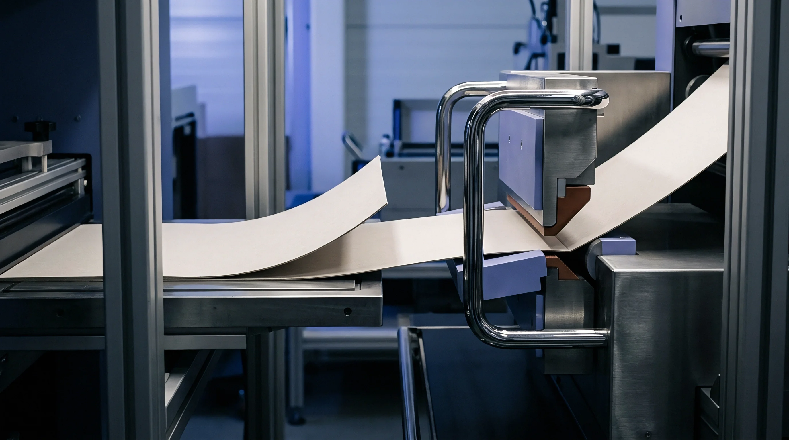
Carton blanks feed through high-speed folder-gluers at rates exceeding fifty thousand units per hour. These machines rely on consistent crease opening forces to fold panels precisely along glue lines. When matrix channels are cut too wide, crease resistance remains excessively high, causing folding belts to slip against carton blanks.
Rigid counterplates eliminate register wander. Skewed cartons pass through adhesive extrusion nozzles, smearing glue over finished decorative surfaces and jamming downstream packing chutes.
Make-ready shims absorb machine deflection. Every die-cutting setup involves precise levelling under the cutting plate to equalize impression pressure across all carton stations on a sheet. When matrix channels fit the paperboard caliper correctly, make-ready crews spend thirty minutes balancing pressure rather than two hours swapping out matrix strips to troubleshoot cracked fold lines.
Faster make-ready cycles yield lower unit costs and protect operating margins across multi-sku production runs.
Procurement Specifications for Cutting Dies
Brand buyers and packaging engineers prevent production disputes by writing precise matrix geometry directly into tooling procurement contracts. Specifying the exact board grade, nominal caliper, creasing rule thickness, and target channel width eliminates ambiguity between design agencies and converting plants. When buying luxury cosmetic cartons with high-build varnish or metallized polyester laminations, engineering drawings specify channel widths that incorporate the total thickness of the substrate plus all laminated film plies.
Standard packaging supply contracts stipulate that delivered cartons must exhibit a crease-to-board stiffness ratio between thirty and fifty percent per ISO 5628 bending tests, a performance metric achievable only when matrix channel dimensions match board properties on the cutting line.