Creasing Matrix Selection Criteria for Multi Ply Folding Boxboard Grades
Select creasing matrix depth equal to FBB board thickness and calculate channel width using rule thickness plus 1.5 times thickness with-grain or 1.7 times across-grain.


Board
Multi-ply cartonboard grades combine distinct fiber furnish layers to optimize bending stiffness per unit weight. Folding boxboard (FBB), classified under industry norms as GC1 or GC2, features double-coated or triple-coated top plies made from bleached chemical pulp, a middle core composed of mechanical pulp or chemithermomechanical pulp (CTMP), and an uncoated or single-coated reverse ply of chemical or mechanical pulp. Understanding the mechanical performance of this layered arrangement during converting requires viewing the sheet as an engineered composite beam subjected to localized shearing and bending forces.
Creasing transforms a rigid planar board into a flexible hinge line without destroying structural continuity. When a creasing rule forces the sheet into a matrix channel, the primary deformation mechanism is controlled internal shear failure. Middle mechanical plies delaminate along internal interfaces, forming a permanent internal bulge or ridge on the reverse side of the board.
This localized internal delamination drops the bending stiffness along the crease line by 60 to 80 percent compared to the uncreased stock, permitting a clean 90-degree or 180-degree fold without surface cracking.
Delamination Mechanics in Mechanical Middle Plies
High-density chemical pulp on outer faces sandwiches high-yield groundwood or chemithermomechanical pulp within the core structure. Chemical pulp provides high tensile strength and elasticity, whereas mechanical core plies provide bulk and z-directional compressible thickness. Plies split under compression.
During rule impact, z-directional tensile stress (measured under ISO 15754 or TAPPI T 541) causes middle mechanical layers to separate along microscopic boundaries. If internal bonding strength in the core is excessively high, the board resists internal shear, forcing strain outward to the top coated liner. Shear stresses control delamination.
High core density prevents internal detachment, causing immediate surface rupture across the clay coating layer.
Conversely, insufficient internal bond strength causes widespread delamination far beyond the rule contact zone. This micro-structural collapse destroys line definition, yielding a sloppy, wide crease with negligible resistance to bulging when glued into a carton shape. The optimum internal bond strength for folding boxboard typically sits between 150 and 250 Joules per square meter, depending on total caliper and grammage.
Mechanical fiber length and yield in the core dictate how cleanly these internal planes separate under impact.
Plies in a 350-micrometre GC1 folding boxboard delaminate internally across a 1.2-millimetre zone when z-directional bonding falls within 160 to 210 Joules per square meter under ISO 15754 conditioning.
Structural Behavior under Creasing Rule Displacement
Penetration of a male steel rule into a virgin cartonboard sheet forces compressive loading along the top liner while generating tensile stresses across the reverse side. The board undergoes three distinct structural transformations in sequence:
- Initial elastic indentation where the top liner conforms to the rounded edge of the creasing rule radius.
- Transverse shear initiation causing inter-ply separation within the bulky CTMP middle core as the sheet is driven into the matrix channel.
- Permanent plastic deformation yielding a raised internal bead on the underside of the sheet that acts as an internal hinge axis during box blank folding.
Fibers bend before breaking. When the matrix channel is too wide or deep, the rule fails to generate sufficient localized shear within the CTMP core, yielding incomplete delamination. When folded on automated packaging equipment, an improperly creased blank demonstrates excessive folding resistance force (ISO 5628), leading to panel bowing, corner skewing, and packaging machine jam-ups on high-speed cartoning lines.
Incorrect matrix sizing permanently compromises carton squareness.
| Grade Designation | Top Layer Furnish | Middle Layer Furnish | Reverse Layer Furnish | Primary Crease Delamination Zone |
|---|---|---|---|---|
| GC1 FBB | Bleached Chemical Pulp (Coated) | Chemithermomechanical Pulp (CTMP) | Bleached Chemical Pulp (White) | Middle CTMP Ply Interfaces |
| GC2 FBB | Bleached Chemical Pulp (Coated) | Mechanical / CTMP Pulp | Unbleached Mechanical / CTMP (Cream) | Core Mechanical Sub-layers |
| SBB / GZ | Bleached Chemical Pulp (Coated) | Bleached Chemical Pulp | Bleached Chemical Pulp (White) | Distributed Throughout Full Thickness |
| SUB / GT | Unbleached Chemical Pulp | Recycled / Waste Paper Plies | Unbleached Chemical Pulp | Inter-ply Recycled Boundaries |

Geometry
Mathematical calculation of channel dimensions relies directly on board caliper, rule thickness, and volumetric compression ratios during impression. Selecting creasing matrix channel dimensions for multi-ply folding boxboard requires precise formulas distinct from those used for solid bleached board or recycled chipboard grades. Because multi-ply FBB features a compressible, thick mechanical core, channel calculations must provide adequate volume to accommodate the displaced internal bead without pinching or splitting the sheet boundaries.
Standard empirical formulas define channel width (W) and channel depth (D) relative to board thickness (tb) and creasing rule thickness (tr). Matrix height governs depth. For multi-ply folding boxboard, channel depth matching the caliper of the board is selected as the baseline, adjusted for matrix compression factors under impression loading.

Mathematical Derivation of Channel Width and Depth
Sizing the channel depth requires matching the target thickness of the cartonboard stock under nominal press impression. The formula for channel depth (D) in FBB stock is direct:
D = tb
Where tb represents nominal board caliper in millimeters. Channel width (W) requires incorporating a multiplier applied to the board thickness to allow the core to bulge downward into the groove without shearing the outer liner faces:
W = tr + (1.5 × tb) quad (for Creasing With Grain)
W = tr + (1.7 × tb) quad (for Creasing Across Grain)
Grain orientation influences bending resistance significantly. Across-grain creases demand wider channel dimensions because cross-direction fibers present higher resistance to transverse folding deformation. Solid bleached board (SBB/GZ) uses a lower factor of 1.4 × tb due to its uniform, high-density chemical fiber composition, whereas FBB demands the larger 1.5 to 1.7 factor to accommodate mechanical pulp displacement without cracking the clay coating layer.

Worked Dimensioning for Four Hundred Micron Stock
Evaluating a 400-micrometre (0.400 mm) GC1 folding boxboard running with a standard 2-point (0.71 mm) creasing rule establishes clear boundary figures. Applying the standard equations produces exact geometrical targets for matrix selection:
Target board thickness (tb) = 0.400 mm. Creasing rule thickness (tr) = 0.71 mm (2 Pt).
Channel Depth Calculation:
D = 0.400 mm
Standard commercial matrix offerings specify nominal depths in 0.05 mm increments. Select a matrix depth of 0.40 mm or 0.45 mm depending on press platen tonnage and matrix shoulder compressibility.
With-Grain Channel Width Calculation:
Wwith = 0.71 + (1.5 × 0.400) = 0.71 + 0.60 = 1.31 mm
Across-Grain Channel Width Calculation:
Wacross = 0.71 + (1.7 × 0.400) = 0.71 + 0.68 = 1.39 mm
Narrow channels crush stock. A matrix profile with a 1.30 mm channel width matches the with-grain calculation, while a 1.40 mm channel width serves the across-grain requirement. Using a 1.30 mm matrix across-grain forces excessive shear, rupturing the top clay coating layer, whereas using a 1.40 mm matrix with-grain yields a soft, poorly defined hinge line.
Creasing matrix channel width for 450-micrometre folding boxboard across-grain requires a minimum calculated opening of 1.47 millimeters when operating with a 2-point rule.
| Board Caliper (mm / µm) | Board Grammage (g/m²) | Calculated Depth D (mm) | With-Grain Width W (mm) | Across-Grain Width W (mm) | Commercial Matrix Size Selected |
|---|---|---|---|---|---|
| 0.300 mm / 300 µm | 215 g/m² | 0.30 mm | 1.16 mm | 1.22 mm | 0.30 x 1.20 mm |
| 0.350 mm / 350 µm | 240 g/m² | 0.35 mm | 1.24 mm | 1.31 mm | 0.35 x 1.30 mm |
| 0.400 mm / 400 µm | 275 g/m² | 0.40 mm | 1.31 mm | 1.39 mm | 0.40 x 1.30 / 1.40 mm |
| 0.450 mm / 450 µm | 300 g/m² | 0.45 mm | 1.39 mm | 1.48 mm | 0.45 x 1.40 / 1.50 mm |
| 0.500 mm / 500 µm | 330 g/m² | 0.50 mm | 1.46 mm | 1.56 mm | 0.50 x 1.50 mm |
| 0.600 mm / 600 µm | 380 g/m² | 0.60 mm | 1.61 mm | 1.73 mm | 0.60 x 1.60 / 1.70 mm |
Determining channel geometry demands selecting dimensions that match the specific thickness of the board rather than using a single matrix size across varied sheet calipers.


Substrate
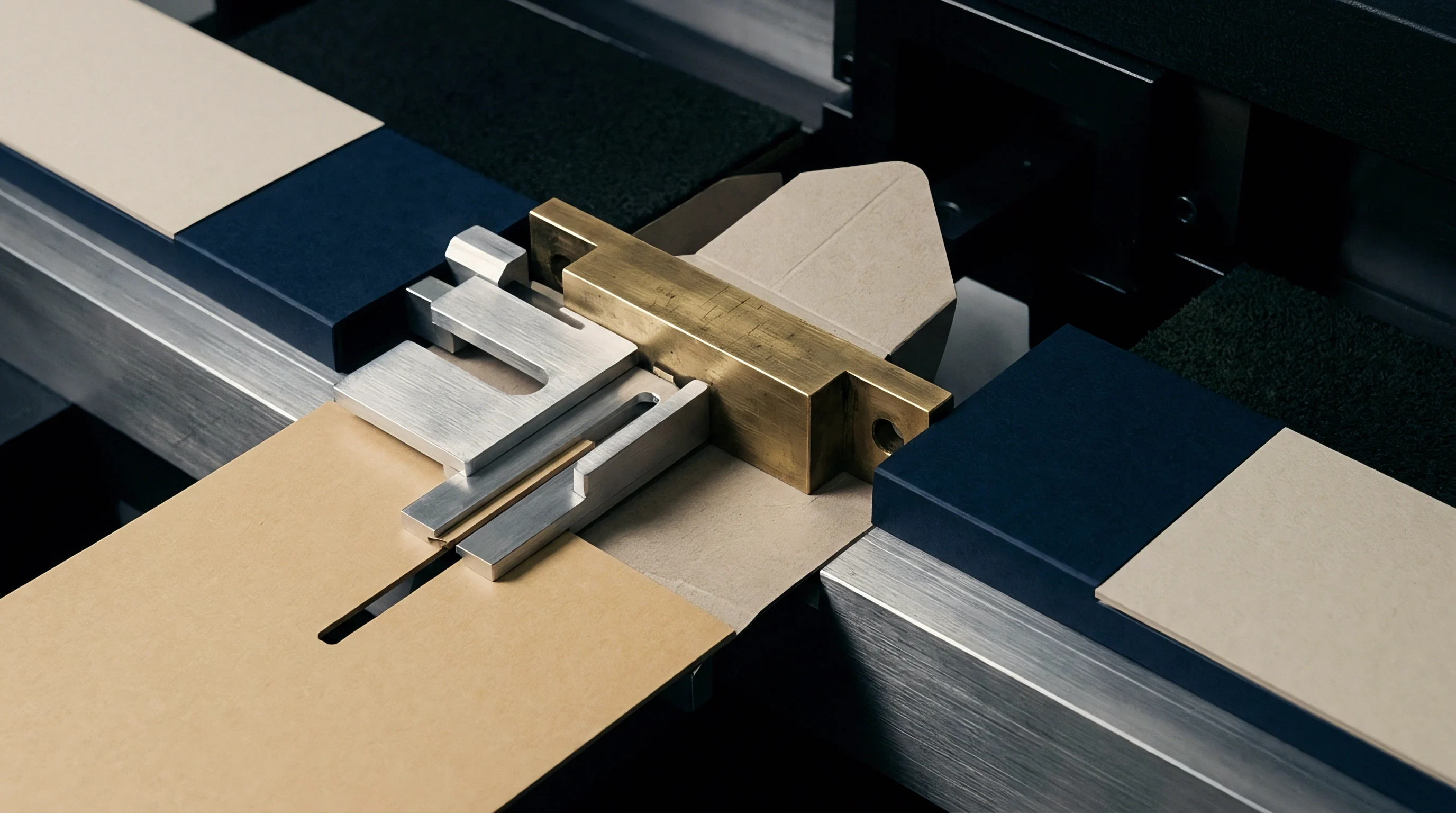
Matrix bases rely on extruded synthetic polymers, micro-thin steel ribbons, or vulcanized fiber compounds anchored to press plates with pressure-sensitive adhesives. Base material properties govern dimensional stability, channel edge sharpness, and press longevity under continuous dynamic impact during extended production runs. Selecting matrix substrates requires evaluating both mechanical deformation characteristics and physical base profiles.
Resin withstands heavy impact. Standard matrix materials fall into three primary physical categories: rigid polyvinyl chloride (PVC), micro-gloss phenolic/epoxy resin compounds, and composite pressboard or vulcanized fiber. Modern high-speed platen die-cutters running at 7,000 to 9,000 sheets per hour impose severe lateral shearing forces against the matrix walls during impression.
Poor material stability causes wall spread, widening the channel opening over time and altering crease definition as the run progresses.

Base Formulations and Dimensional Stability under Shear
High-run converting lines subject matrix channels to millions of cyclic impacts from heavy steel rules. Rigid PVC bases offer low cost and easy cutting during hand-fitting, but experience lateral flow under high platen pressure. Wall spread on PVC matrix channels typically reaches 0.05 mm to 0.10 mm after 50,000 impressions, leading to softer crease lines and reduced fold accuracy.
Phenolic resin matrix compositions exhibit minimal plastic deformation, holding critical tolerances within 0.01 mm past 200,000 impressions.
Composite fiber base systems provide excellent thermal stability when cutting plates warm up during continuous high-speed runs. Steel micro-matrix options feature ultra-thin spring steel bases bonded to precision plastic channel walls, eliminating shoulder height variations while preventing sheet snagging during rapid die-cutter press feeding.
Specialized Profiles for Complex Blank Geometry
Tight rule configurations present physical constraints where adjacent matrix shoulders collide on the cutting plate. Standard matrix channels feature symmetric shoulder walls on both sides of the groove. When creasing lines sit closer than 4.0 mm apart, standard shoulders overlap, causing matrix detachment or uneven board support during compression.
Specialized channel profiles resolve these physical interference issues:
- Off-Center Profiles locate the channel off-center on the adhesive base, allowing close positioning to adjacent die components, cut lines, or embossed features without trimming matrix walls by hand.
- Double-Crease Profiles provide two precisely spaced parallel channels on a single base ribbon, ensuring exact pitch consistency for double-hinge carton spines and folder flaps.
- Micro-Matrix Profiles feature narrowed, low-profile outer shoulders that minimize sheet drag and static pick-up on lightweight folding boxboard running on high-speed automatic platens.
- Chamfered Shoulder Profiles integrate angled outer ramps that allow the lead edge of the sheet to slide smoothly over the matrix without catching or causing sheet registration stops.
A matrix strip supplier will occasionally state that a single standard center-channel profile can handle any job layout if operator make-ready pressure is boosted. This claim ignores the lateral sheet distortion, shoulder collision, and edge-snagging failures that inevitably occur on complex blank layouts under high-speed automatic feeding.
| Matrix Base Material | Dimensional Stability | Max Impression Life | Trimming Workability | Base Thickness Below Board |
|---|---|---|---|---|
| Standard Extruded PVC | Moderate (Wall spread at 50k) | 50,000 – 80,000 | Excellent (Soft cut) | 0.18 mm – 0.22 mm |
| Phenolic Resin Composite | High (Minimal deformation) | 200,000 – 350,000 | Fair (Requires sharp cutters) | 0.12 mm – 0.15 mm |
| Steel Micro-Matrix Base | Extreme (Zero creep under load) | 500,000+ | Specialized tool required | 0.08 mm – 0.10 mm |
| Pressboard / Vulcanized Fiber | Good (Absorbs thermal expansion) | 100,000 – 150,000 | Good (Clean shear) | 0.15 mm – 0.18 mm |

Defects
Surface cracking and inner ply rupture stem directly from mismatched matrix dimensions, poor rule profiles, or improper moisture conditioning. Diagnosing crease defects requires establishing clear mechanical links between visual defects on the carton flap and root-cause parameters during die-cutting make-ready.
Top liner cracking represents the most common defect encountered when converting multi-ply folding boxboard. Double-coated clay surfaces are rigid and brittle under tension. When a crease line folds 180 degrees, the outer coated fibers undergo extreme elongation.
If internal delamination within the mechanical core failed to occur during creasing, all tensile strain concentrates directly on the outer coated ply, exceeding its ultimate tensile elongation limit (typically 1.5% to 2.2%) and causing visible white line fracturing.

Root Cause Analysis of Outer Liner Fracture
Splitting along the top coated surface during 180-degree folding indicates excessive tensile strain across the outer fiber network. Narrow channel widths force the creasing rule to pinch the stock against the matrix channel edges, acting as a shear punch rather than a gentle bending former. This pinching action cuts outer fibers before internal core delamination completes.
Rule bevel selection also directly dictates liner strain. Standard creasing rules feature a fully rounded radius (typically 0.35 mm radius on a 2-point rule). Using a sharp or narrow-radius rule concentrates shear stress on a narrow line, rupturing top coatings.
Replacing standard rounded rules with micro-bevel or flat-faced creasing rules on heavy FBB calipers distributes initial impression load over a wider contact patch, encouraging core delamination while protecting brittle clay topcoats.
Environmental Moisture and Coating Brittleness Interactions
Ambient humidity levels in converter storage facilities directly govern fiber network elasticity. Paperboard equilibrated under ISO 187 standard conditions (23°C, 50% Relative Humidity) retains an equilibrium moisture content between 6.5% and 7.5% by weight. Moisture dictates fracture boundaries.
Dry winter pressrooms running ambient humidity below 30% RH reduce board moisture content below 5.0%, rendering mechanical pulp fibers rigid and clay coatings brittle.
Board stored in cold warehouses and brought immediately to warm, dry pressrooms loses surface moisture rapidly. Decreased moisture reduces the strain-to-break limit of top liners, turning previously acceptable matrix dimensions into a source of severe liner cracking. Applying water mist to sheet edges or installing pressroom humidification systems restores fiber elasticity, preventing surface fracture without altering established matrix geometry.
Cartonboard conditioned below five percent total moisture content exhibits a forty percent reduction in top-liner strain capacity, causing score line cracking on standard channel geometries.
Systematic troubleshooting of crease defects requires evaluating physical failure symptoms against specific matrix adjustments:
- Verify outer liner surface for cracking: increase matrix channel width by 0.10 mm increments or shift from a 2-point to a 1.5-point creasing rule to relieve liner tension.
- Inspect reverse side bead for shear cutting: decrease rule penetration height or select a matrix depth 0.05 mm less than nominal board thickness.
- Check crease line straightness and fish-tailing: audit matrix locator bridge fit to ensure zero lateral play during initial matrix transfer to the cutting plate.
- Evaluate folding force resistance: verify core delamination by tearing open a crease cross-section to confirm visible internal ply separation across the mechanical pulp layer.
Which matrix material formulation prevents poly-coated liner splitting on frozen food cartons?

Commerce
Selection decisions between individual matrix strips, counter-die pressboard plates, and photo-etched steel plates dictate job tooling expenses and set-up waste. Tooling selection drives margin. Financial calculation of creasing tooling requires balancing fixed die-making costs against variable make-ready downtime on high-speed press lines.
Self-adhesive plastic matrix strips present low upfront tooling expenditure. Installing matrix strips manually across a complex 12-up carton layout requires 30 to 45 minutes of press operator make-ready time. For short production runs under 20,000 sheets, matrix strips deliver optimal economic returns because total job setup costs stay low despite operator labor time.

Break-Even Thresholds for Pertinax versus Channel Matrix
Operational expenditure during press make-ready depends heavily on carton layout complexity and run volume. High-density resin plates (commonly known as Pertinax counter-dies) or CNC-milled steel counter-plates eliminate manual channel cutting entirely. A Pertinax counter-plate contains all crease channels, chamfers, and locator holes pre-milled into a single rigid panel that pins directly onto the cutting plate in under five minutes.
Waste escalates rapidly. Press downtime on a modern 106-centimeter automatic die-cutter costs between 150 and 250 Euros per hour. Reducing make-ready setup time from 45 minutes to 10 minutes saves 35 minutes of chargeable press capacity per job changeover.
On repeat jobs or long runs exceeding 50,000 sheets, the higher initial cost of a Pertinax counter-plate (typically 120 to 200 Euros per job) is offset by saved press room operating hours and zero matrix wall wear.

Folder-Gluer Downtime and Pressroom Waste Mechanics
Poorly creased carton blanks cause misfeeds, jam-ups, and squareness faults on high-speed gluing machines running at 400 meters per minute. A single defective crease line that fails to fold cleanly at the pre-folder station triggers automatic sensor stops, dumping dozens of blanks into waste chutes and halting production lines.
Substandard creasing matrix selection directly elevates spoilage rates during gluing and packing passes. Operating with worn PVC matrix channels causes variable crease stiffness across a single impression sheet, forcing gluer operators to slow press throughput by 20% to 30% to prevent box jamming. Slower line speeds and elevated scrap rates eliminate any initial cost savings achieved by purchasing low-grade channel matrix strips.
| Tooling System | Initial Tooling Cost (EUR) | Make-Ready Setup Time | Channel Wear Resistance | Break-Even Point (Sheet Volume) |
|---|---|---|---|---|
| Standard PVC Matrix Strips | 15 – 30 EUR per set | 35 – 50 Minutes | Low (Degrades at 60k) | Under 15,000 Sheets |
| Phenolic Resin Matrix Strips | 30 – 60 EUR per set | 35 – 50 Minutes | High (Stable to 250k) | 15,000 – 50,000 Sheets |
| CNC-Milled Pertinax Counter | 120 – 220 EUR per plate | 5 – 10 Minutes | Very High (Stable to 350k) | 50,000 – 150,000 Sheets |
| Milled Steel Counter-Plate | 450 – 800 EUR per plate | 5 – 8 Minutes | Extreme (1,000,000+) | Over 150,000 Sheets |
Standard quality assurance clauses in supply agreements specify that carton blanks delivered to automated packing lines must maintain crease bending resistance within a strict tolerance band of plus or minus 15 percent under DIN 55437 testing. Exceeding this boundary transfers financial liability for packaging line downtime directly to the packaging converter.