Determining Z Direction Compression Coefficients for Embossing Die Cavity Tooling
Calculate Z-direction cavity tooling depth by multiplying uncompressed caliper by the plastic strain coefficient and adding targeted visual relief height.
Caliper
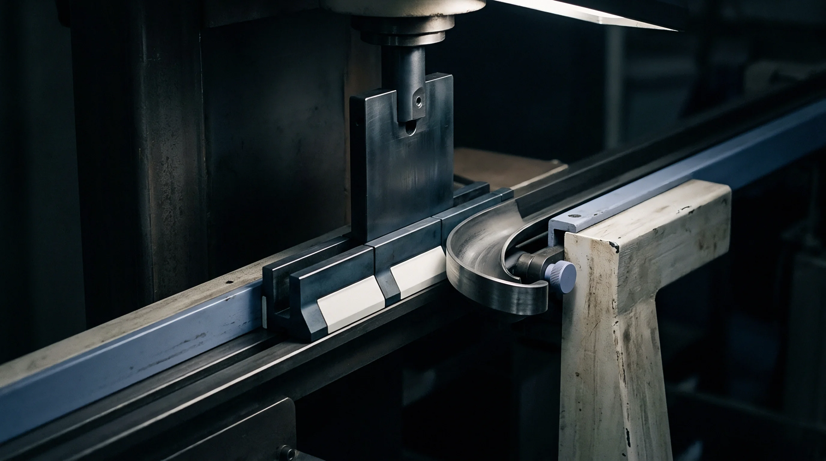
Board thickness governs initial displacement. When a flatbed platen drives a brass embossing die into multi-ply paperboard, transverse deformation splits into elastic deflection, delayed viscoelastic creep, and unrecoverable plastic compaction. Toolmakers who treat packaging substrate as an incompressible solid sink female die cavities too deep, creating carton perforation along embossed perimeters.
Setting tooling depth requires an exact measurement of out-of-plane mechanical compliance under rapid loading rates. Platen stroke cycles between fifteen and eighty milliseconds concentrate compressive stress along the Z-axis, collapsing inter-fiber hydrogen bonds and crushing internal void space.
Fiber composition dictates the compression threshold. Solid bleached sulfate boards, formed from chemical wood pulp, feature flexible fibers that compact uniformly under mechanical load. Folding boxboard incorporates a thick mechanical pulp center between chemical pulp liners.
That mechanical core retains substantial bulk and stiffness, yielding distinct transverse compaction mechanics during impact. Unbleached kraft liners withstand high transverse shear stress without internal delamination, whereas white lined chipboard contains recycled secondary fibers with shortened lengths and degraded bonding potential. Microstructural variations alter the board’s true transverse compressive modulus, meaning an identical die profile pressed into distinct grades produces divergent relief heights.
- Inter-fiber shear fracture develops when high local pressure forces the surface ply past its elongation limit along female cavity perimeters.
- Delamination of internal plies arises from mismatched transverse shear modulus between chemical outer plies and mechanical core plies.
- Porous void compaction occurs across mechanical furnish centers, reducing board insulation properties and changing post-emboss carton rigidity.
- Coating chalking results from inorganic pigment layers fracturing under severe local strain while base fibers compress underneath.
Density climbs steeply under load. Initial transverse displacement encounters low resistance while loose surface fibers flatten and internal air voids collapse. Resistance rises exponentially once fiber cell walls make direct contact.
Measuring this non-linear response requires high-rate acoustic transducers or specialized platen load-displacement cells capable of sub-millisecond data recording. Static micrometer measurements fail because paperboard exhibits substantial time-dependent mechanical recovery. A caliper reading taken thirty seconds after press release captures elastic springback, hiding the maximum deformation reached at peak platen bottom-dead-center.
Solid bleached sulfate compressed at 18 megapascals under twenty milliseconds of platen contact retains fifty-eight percent of its permanent mechanical displacement after forty-eight hours.
Moisture softens the hemicellulose matrix. Changes in ambient converting humidity shift the board equilibrium moisture content, altering transverse fiber pliability. Water molecules enter amorphous cellulose domains, acting as molecular plasticizers that lower the transverse compressive yield strength.
A board conditioned at sixty-five percent relative humidity compresses thirty percent further under identical platen tonnage than the identical board processed at forty percent relative humidity. Cavity depths machined for dry winter converting conditions crush excessively when seasonal humidity increases without tooling adjustment.
Ignoring substrate Z-axis compaction properties during female engraving generation produces cracked outer carton faces, split lamination films, and rejected production runs that demand complete die remanufacturing.
Cavity
Female engraving depths dictate the maximum physical displacement an embossed fiber structure can achieve. Translating a designer’s vector art into three-dimensional metal demands calculating the exact ratio between uncompressed sheet caliper and compacted post-strike board thickness. When an engraving program mills a pocket one millimeter deep for a five-hundred-micrometer board, the board cannot fill the void without stretching across cavity edges.
The fiber web spans the opening, drawing substrate inward through lateral tension. True embossing relief forms through controlled transverse compaction combined with out-of-plane tensile elongation.
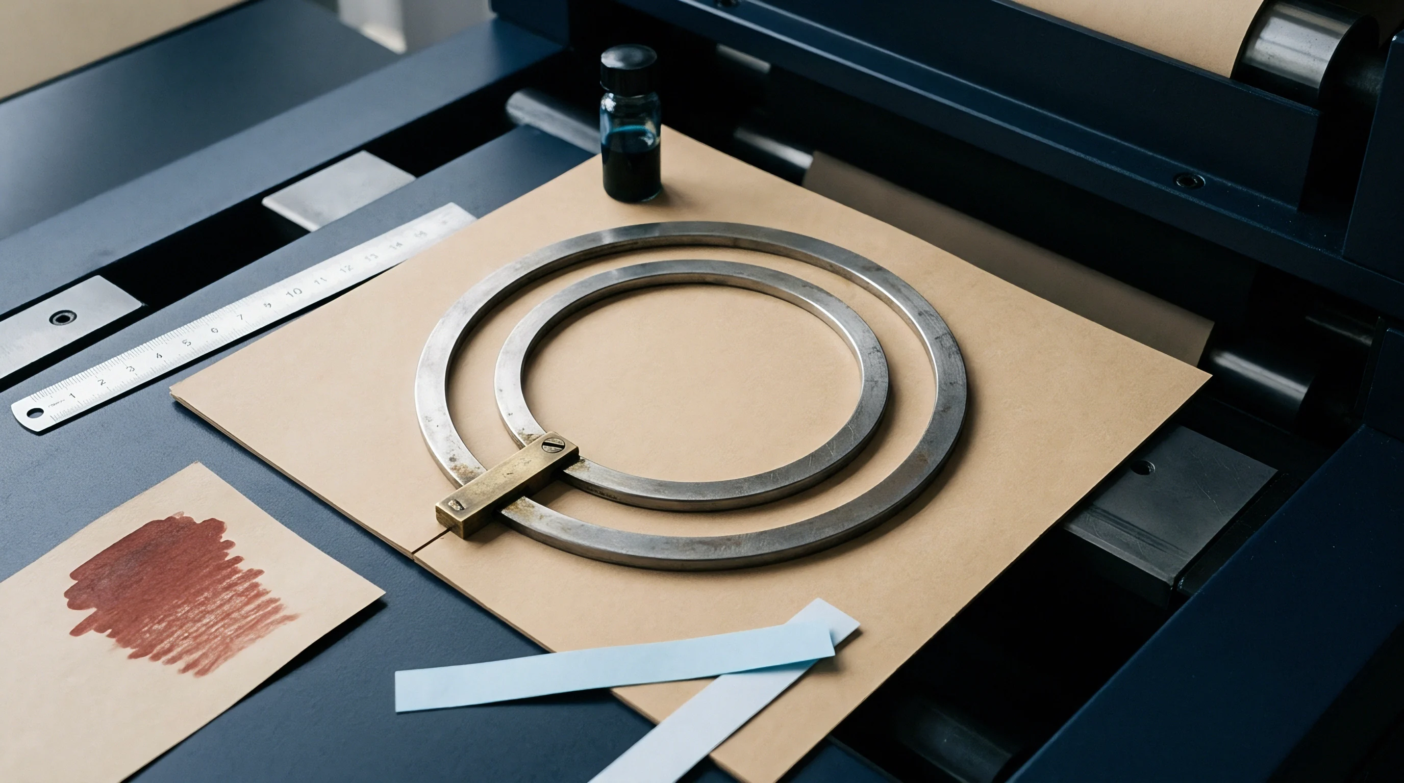
What Governs Cavity Depth Sinking Ratios?
Tooling paths require defined compression coefficients to establish base pocket depths and edge floor elevations. Calculating the transverse compression coefficient, expressed as the ratio of compressed caliper under peak load to initial uncompressed caliper, provides the baseline for cavity depth. For premium virgin cartonboard, this coefficient ranges between 0.45 and 0.65 under typical converting pressures of fifteen to twenty-five megapascals.
Toolmakers assign cavity floor depths equal to the targeted visual relief height plus the compressed thickness of the substrate. If the target emboss height measures two hundred micrometers on a four-hundred-micrometer board with a compression coefficient of 0.50, the cavity floor must sit at four hundred micrometers from the die face.
| Board Classification | Grammage (g/m²) | Uncompressed Thickness (µm) | Transient Compression Modulus (MPa) | Permanent Plastic Strain Ratio | Recommended Cavity Depth Factor |
|---|---|---|---|---|---|
| Solid Bleached Sulfate (SBS) | 350 | 450 | 42.5 | 0.52 | 0.78 |
| Folding Boxboard (FBB) | 300 | 490 | 28.4 | 0.61 | 0.68 |
| White Lined Chipboard (WLC) | 380 | 510 | 34.1 | 0.58 | 0.72 |
| Coated Kraft Back (CKB) | 330 | 460 | 51.2 | 0.46 | 0.84 |
Lateral confinement alters true response. High-density graphics with tight typographic strokes trap board between steep metal walls, restricting horizontal fiber Poisson expansion. Under complete lateral constraint, cellulose matrices display elevated resistance to transverse compression, driving hydraulic-like backpressure into the platen bed.
Toolpaths must relieve this hydrostatic fiber stress by incorporating micro-radiuses along inside engraving corners. A sharp interior corner generates localized stress concentrations that rupture multi-layer barrier coatings or break metallized film laminations.
Toolmakers increase female cavity depth when converting multiply recycled grades to balance fiber springback against surface liner rupture.
Relief height stability depends on the ratio of elastic recovery to permanent plastic deformation. Board compressed beyond its elastic limit retains its deformed shape indefinitely, establishing crisp visual contrast. Solid bleached sulfate recovers quickly.
Recycled fibers exhibit slower recovery. Mechanical springback defies simple linear scaling. When cavity depth sits too shallow, the male counter fails to drive fibers past their yield point, causing the relief to flatten under pallet stacking pressures during distribution warehouse storage.
Cavity floors must remain shallower on multi-ply mechanical boards than on chemical pulp sheets to preserve the structural rigidity of the uncompressed packaging container.
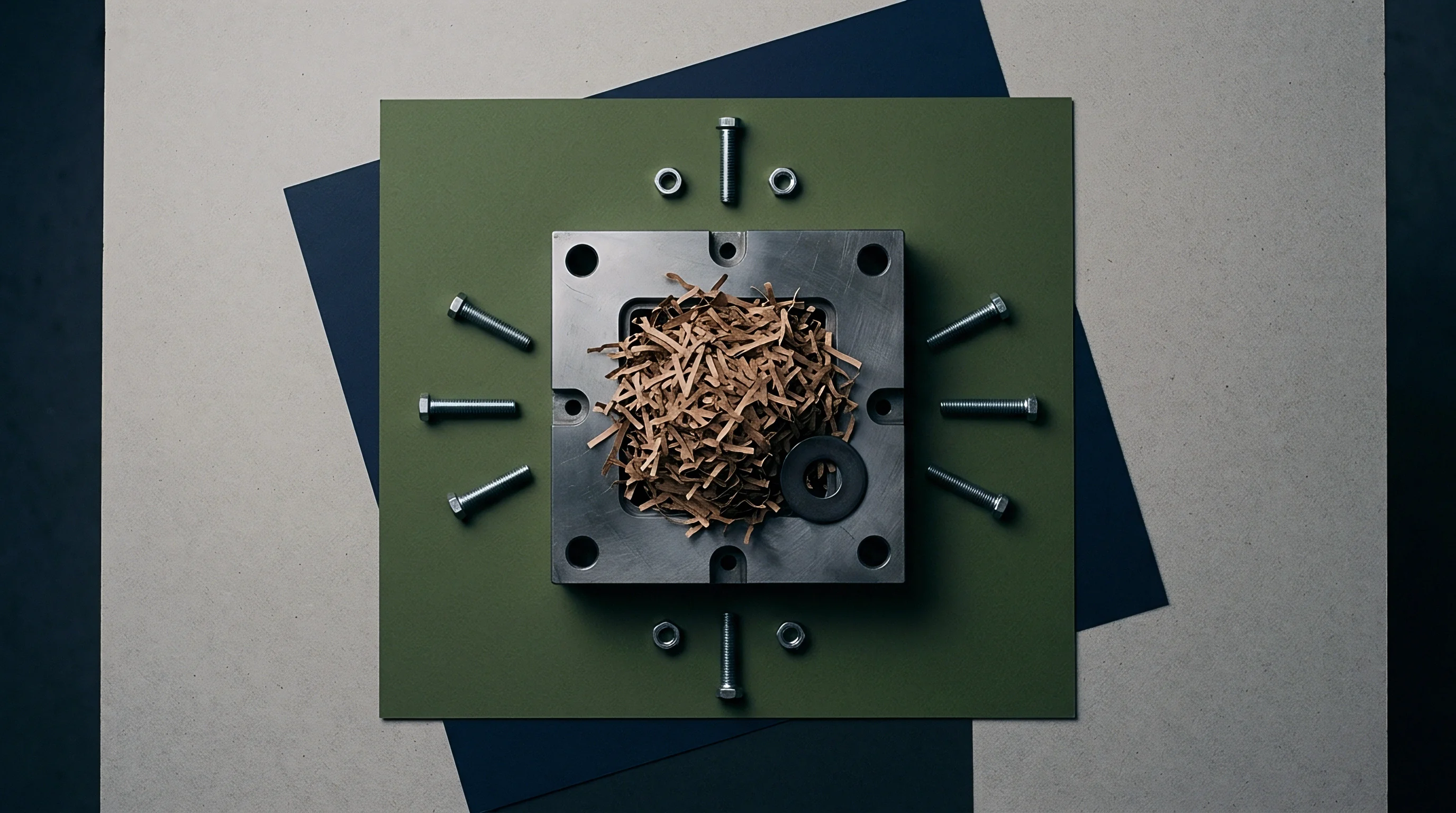
Plate
Counter dies provide the opposing force that pushes packaging board into female tooling recesses. Whether constructed from cast polyurethane, milled fiberglass-reinforced epoxy, or etched brass, the male matrix mirrors female cavity geometry while incorporating clearance offsets. If a male plate features identical dimensions to the female die minus nominal board caliper, the press locks up or shears the sheet along pattern borders.
The male contour profile must reflect the exact compressed board thickness across every flat, slope, and radius.
- Platen baseline leveling establishes parallel alignment between the upper chase and lower bed before mounting tooling, preventing uneven pressure distribution across the sheet width.
- Thermal stabilization run brings brass dies and steel chases to an operational temperature of forty-five degrees Celsius, expanding metal elements before finalizing matrix positions.
- Strike impression pull uses calibrated carbon film to verify contact distribution, pinpointing zones of excessive edge shear or insufficient apex pressure.
- Selective patch make-ready positions tissue shims beneath the counter die base plate, raising low relief segments without increasing general platen tonnage.
Counter dies impose localized shear. As the male apex enters the female opening, paperboard bends over the male perimeter radius while sliding down the female sidewall. Tensile stresses build along the outer linerboard face while compressive stresses dominate the inner ply.
Counter die materials possess finite hardness ratings, typically measuring eighty to ninety-five Shore D for cast resins. Softer counter materials compress under continuous cyclic pressure, increasing effective cavity clearance after ten thousand press impressions and softening the crispness of the embossed detail.
Male counter force concentrates on the perimeter radiuses long before the floor of the relief makes contact.
Tooling geometry dictates edge shear. When counter clearances fail to match the board compression coefficient, the sheet experiences tensile tearing along foil-stamped borders. The converter balances platen tonnage against visual relief sharpness.
Excess tonnage compacts the sheet until paper caliper drops to forty percent of initial values, fracturing clay coating layers and revealing raw cellulose fibers beneath pigmented print surfaces. Controlled counter profiling prevents linerboard fracture while maintaining defined tactile embossing borders.
Commercial tooling orders governed by DIN 874 flatness tolerances establish that platen alignment variances exceeding fifteen micrometers across five hundred millimeters void tooling perimeter clearance guarantees.

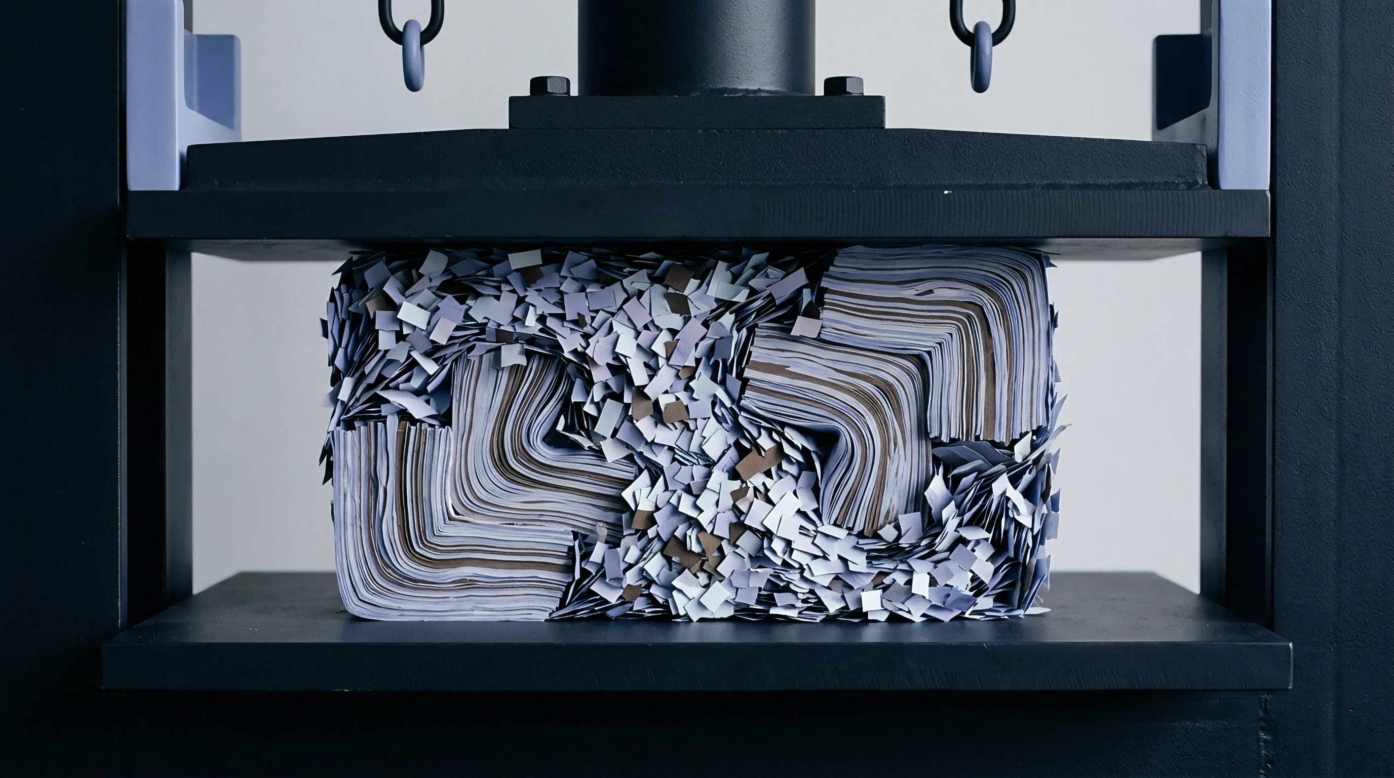
Draft
Sidewall angles relieve lateral friction during platen opening and closure cycles. Vertical cavity faces trap compressed paperboard inside the female die, causing sheet hesitation, gripper pull-out, and register drift. Machining sidewalls with calibrated bevel angles enables smooth sheet release while distributing transverse shear stresses over a wider board surface.
Draft angles typically span thirty to seventy degrees relative to the die face, depending on engraving depth, substrate thickness, and board surface coatings.
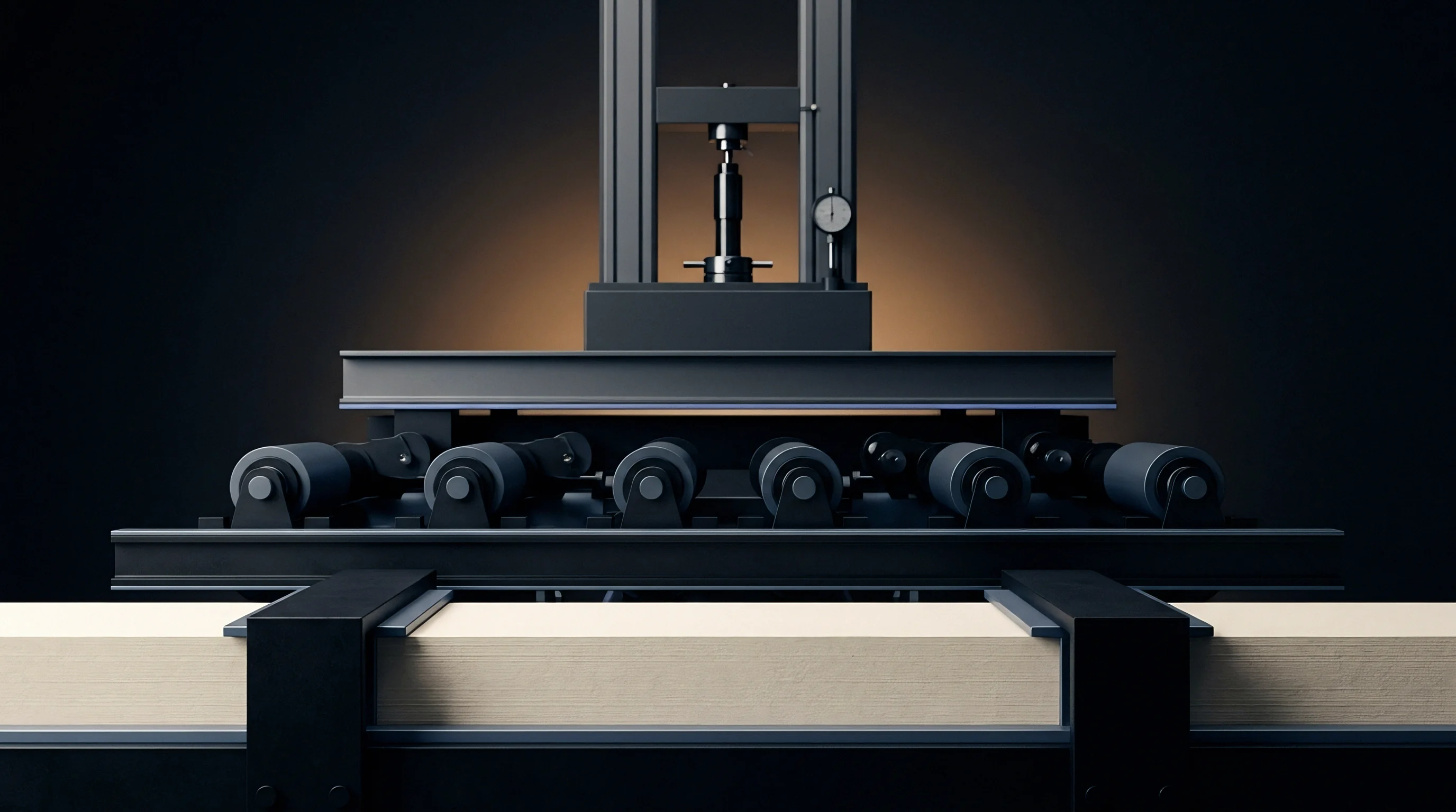
Which Compliance Factors Shift Sidewall Relief Angles?
Extensible virgin fibers tolerate steep sixty-degree sidewalls without delaminating. Recycled boards require gentler forty-five-degree bevels to prevent edge tearing. Coating formulations also dictate bevel angles.
High-gloss polymer coatings and barrier films stretch along inclined metal faces without scuffing, whereas heavy mineral pigment layers crack if pulled across abrupt angles under load. Selecting draft angles connects directly to the substrate compression coefficient: materials with low compression coefficients transfer higher lateral loads to cavity walls, demanding broader angles to facilitate clean part ejection.
- Low bulk chemical grades accept steep draft angles between fifty-five and sixty-five degrees because dense fiber networks support sharp shear deformation without internal rupture.
- Bulky mechanical pulp cores demand broader forty to fifty-degree angles, distributing compressive force across the delicate middle ply to avoid localized core collapse.
- Double-side poly-coated boards necessitate polished draft faces with sixty-degree slopes to eliminate film sticking caused by frictional heat during sustained press runs.
- Embossed foil combinations require minimum forty-five-degree bevels to ensure hot stamping foil adhesive layers release cleanly without edge micro-serration.
Brass holds acute apex profiles. Copper pits under continuous cycling. Aluminum lacks the structural density for extended runs above one hundred thousand impressions.
Toolmakers cut cavity walls using multi-axis high-speed CNC milling cutters running up to sixty thousand revolutions per minute. Conical carbide engraving bits determine the minimum draft angle through their native flute geometry. Machining fine filigree patterns necessitates thirty-degree included angle cutters, leaving steep draft walls that challenge fibrous packaging boards.
Make-ready operators must run higher platen heat to soften board lignins when draft walls exceed fifty-five degrees.
ISO 187 conditioning mandates twenty-three degrees Celsius and fifty percent relative humidity before platen tooling tolerances apply to certified production sheets.
Dwell time governs viscous relaxation. Platen presses running at two thousand sheets per hour allow forty milliseconds of dwell at impression center, whereas modern rotary embossers operating at three hundred meters per minute provide less than five milliseconds of nip contact. High-speed lines require deeper cavity drafts and reduced clearance offsets because short dwell times prevent fibers from completing their plastic deformation cycle.
Board exiting a rapid nip springs back aggressively, scraping vertical cavity walls unless draft angles provide clearance.
Tool suppliers frequently claim that visible carton edge tearing stems from operator over-pressure on make-ready rather than incorrect CNC cutter bevel selection during cavity manufacture.
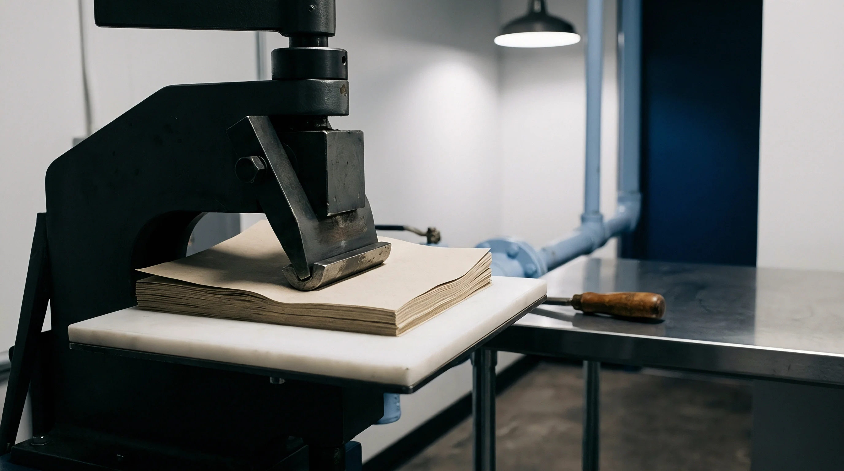
Clearance
Tooling gap calculations establish the mechanical space separating male counters from female cavities. Correct cavity clearance equals the base board caliper multiplied by the transverse compression coefficient across the relief zone. Setting clearance too tight crushes the board past its structural recovery limit, destroying box stacking strength.
Setting clearance too loose leaves fibers unformed, yielding muddy typography and washed-out textures. Toolmakers evaluate the interplay between sheet grammage, furnish density, and press operational velocity to program perimeter tool offsets.
| Target Relief Height (µm) | Board Caliper (µm) | Calculated Z-Axis Deflection (µm) | Female Cavity Depth (µm) | Male Counter Height (µm) | Lateral Perimeter Clearance (µm) |
|---|---|---|---|---|---|
| 150 | 350 | 140 | 360 | 210 | 210 |
| 200 | 450 | 190 | 460 | 260 | 270 |
| 250 | 550 | 245 | 555 | 305 | 330 |
| 300 | 650 | 310 | 640 | 340 | 390 |
| Calculations assume sixty-degree sidewall draft angles and room-temperature platen action on conditioned folding boxboard. | |||||
Perimeter clearances must account for board displacement during multi-level sculptured embossing. When a central relief feature sinks four hundred micrometers, adjacent outer borders pull inward, thinning the surrounding sheet by ten to fifteen percent before male contact occurs. Toolmakers offset perimeter clearances progressively, widening the gap along multi-level boundaries to prevent sheet pinch.
Register shifts ruin fine relief. A lateral register movement of thirty micrometers shifts clearances unevenly, causing one side of an embossed letter to split while the opposing edge remains unformed.
Fiber bonds yield under load. Calculating clearances across combination foil and embossing dies adds another mechanical variable. Stamping foil polyester carrier films measure twelve micrometers in base thickness, accompanied by hot-melt size layers and vapor-deposited aluminum.
The carrier film enters the tooling cavity alongside the paperboard, acting as a flexible compressive membrane that transmits platen pressure while absorbing clearance tolerances. Tooling clearance on hot foil embossing dies must accommodate the combined compressed thickness of both foil carrier and board plies at stamping temperatures exceeding one hundred ten degrees Celsius.
Platen deflection changes edge clearance. Large-format sheetfed platens deflect slightly along their centerlines under full tonnage, producing deeper effective impressions on sheet borders than across central carton layouts. Skilled toolmakers incorporate crowning compensations into counter dies or mill zoned clearance variances directly into the brass plate.
Verifying these dimensional offsets requires physical drawdowns pulled on production stock at operational press temperatures, establishing baseline quality metrics before approving long-run packaging production.
The unresolved mechanical variable remains whether acoustic resonance testing during static sheet intake can predict high-speed platen compression coefficients accurately enough to eliminate physical press make-ready trials entirely.