Predicting Fiber Structure Shear Failure Limits in Multi Ply Coated Recycled Boards
Calculating internal dynamic shear stress against wet-end starch cohesion prevents inter-ply delamination during high-speed folding of recycled boards.
Strata
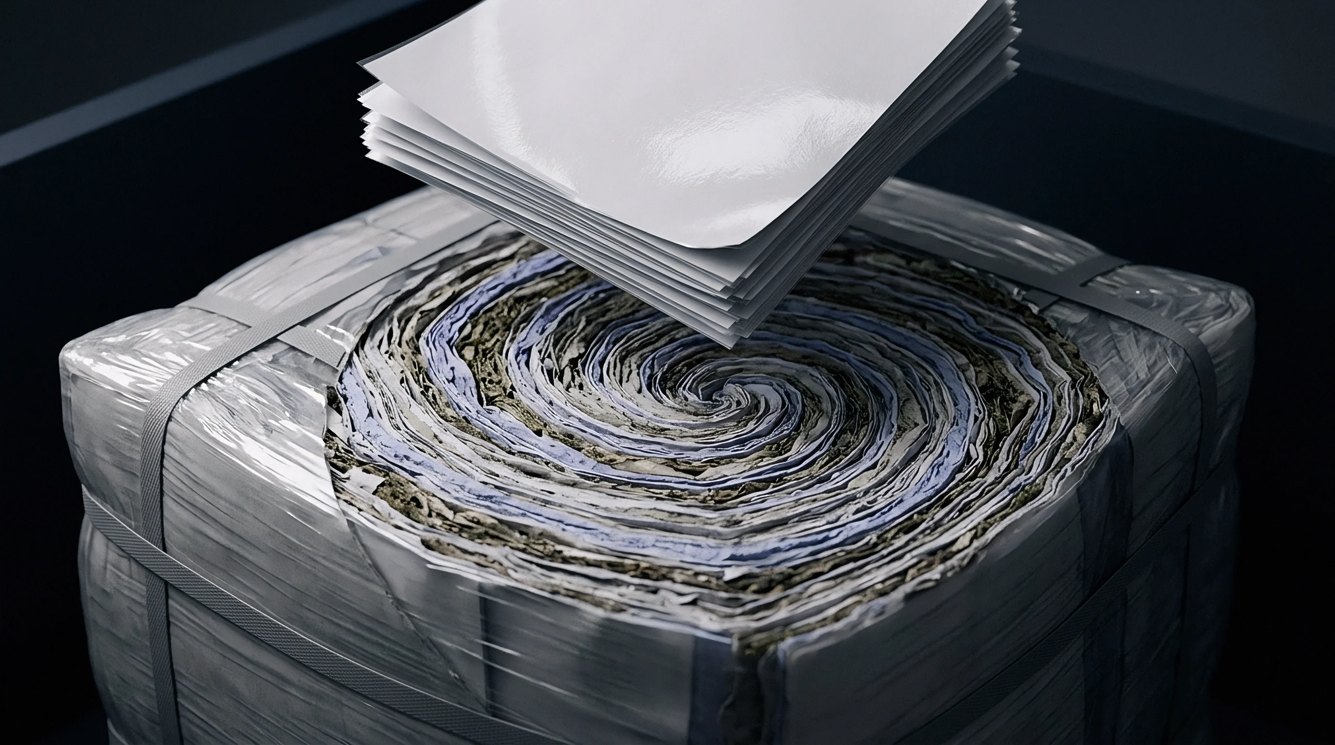
White-lined chipboard gains its bending stiffness from layering different fiber grades across multiple wet-end vats. Placing virgin chemical pulp or clean de-inked furnish on the top liner reserves the bulkier middle plies for cheaper post-consumer recovered paper. How the board behaves under bending loads comes down to the bond strength between these individual plies.
During converting, flexural forces set up tension along the outer liner, compression on the back liner, and internal shear concentrated along the plane of the middle plies.
Recycled grades like GD2, GD3, and GT2 rely on short, hornified fibers throughout their center plies. Successive repulping and drying cycles alter the cell walls, cutting internal swelling and stripping out micro-fibrils. As a result, post-consumer furnish cannot match the natural bonding strength of virgin kraft.
Mills make up for this deficit by spraying cationic starch between the wet webs on multi-wire machines, laying down an adhesive layer to tie the fiber networks together before pressing and drying.
A cationic starch application rate below 3.5 grams per square meter at the middle-ply wet end interface reduces internal bond strength below 110 Joules per square meter under ISO 187 conditioning.

Ply Configuration and Recycled Furnish Gradient
Commercial cartonboard divides mechanical duties between its surfaces and internal volume. The top liner, typically short hardwood bleached kraft or high-brightness de-inked pulp, delivers a smooth, printable surface. Underneath, a thin under-liner masks the dark recycled core.
The core plies account for sixty to eighty percent of the total grammage, run from mixed recovered paper, old corrugated containers, or boxboard cuttings.
Top liners carry primary tension, while the back ply facing the carton interior absorbs heavy compressive strain during carton erection. Middle plies absorb the shear generated as outer layers slide past one another in bending. Packed with degraded, short fibers, this core is the weakest zone of the board, meaning shear failure almost always runs through the center webs or along the boundary where the core meets the under-liner.
Interfacial Starch Stiffening at the Wet End
Spraying starch slurries between wet plies helps recover the cohesion lost to recycled furnish. On multi-fourdrinier or multi-former machines, uncooked corn or potato starch settles onto the wet web at six to ten percent dry solids just before plies merge at the press section. As the sheet passes steam-heated cylinders, the starch gelatinizes around sixty-five degrees Celsius, penetrating adjacent fiber mats to set up a continuous polymer matrix as moisture cooks out.
Uneven spray coverage creates localized boundary weaknesses. If applied too wet, starch migrates into core voids instead of anchoring the seam; if drying temperatures lag, ungelatinized granules remain behind as stress risers under mechanical load. Controlling starch viscosity, nozzle pressures, and dryer temperature profiles ultimately sets the z-directional shear resistance of the finished board.
Contract caliper specifications often treat minor ply separation during sharp folding as commercially acceptable, though converting lines require continuous inter-ply adhesion to prevent score cracking.

Cohesion
Internal shear resistance governs whether a carton survives high-speed converting and folding without popping open. Bending a sheet drives the top liner into tension and the bottom into compression, forcing adjacent plies to slide across each other. The board’s internal shear strength is simply its ability to resist that sliding motion.
Elastic anisotropy in recycled stock makes stress modeling tricky. In-plane elastic moduli in machine and cross directions run between two and eight Gigapascals, but the out-of-plane modulus drops to ten to fifty Megapascals. Interfacial sliding strain follows the shear modulus perpendicular to the board plane; low values allow large displacements between plies, triggering premature delamination once local shear exceeds the network’s bond limit.

Shear Stress Distribution across Board Thickness
Bending cartonboard generates a parabolic shear stress profile that peaks along the centerline. Modeled as a laminated beam, transverse shear varies with applied load and the first moment of area, and inversely with sheet width and moment of inertia. Because peak shear coincides with the weakest, recycled middle plies, core shear failure is common.
Controlled micro-delamination absorbs local bending energy, allowing the board to wrap around tight scoring rules without tearing the coated top liner. If internal bonding is too strong, the plies cannot slip, throwing tensile strain directly into the coating and cracking the surface. If cohesion is too low, the sheet ruptures completely, leaving the blank limp and unworkable on packaging machinery.

Micro-Mechanical Breakdown of Recycled Fiber Networks
Recycling progressively shortens fibers and strips away the secondary wall fibrils that drive hydrogen bonding. Hornification prevents lumens from collapsing, yielding stiff fibers that pack poorly during consolidation. When sheared, these plies fail along two distinct paths: fiber pull-out or cell wall rupture.
Where hornified fibers rely mainly on hydrogen bonding, failure takes the low-energy route of fiber pull-out. Adding cationic starch at the wet end forces the fracture into the fiber walls themselves, tearing them apart. Blending longer virgin kraft into the core increases energy dissipation by forcing fracture paths through complex pull-out geometries instead of clean planar cleavage.
| Grade Class | Grammage (gsm) | Z-Tensile Strength (kPa) | Scott Bond Energy (J/m²) | Shear Modulus Gxz (MPa) | Critical Shear Stress (kPa) |
|---|---|---|---|---|---|
| GD2 Recycled Chipboard | 280 | 310 | 125 | 18.5 | 115 |
| GD2 Recycled Chipboard | 350 | 295 | 110 | 16.2 | 105 |
| GT2 White Lined Chipboard | 300 | 340 | 140 | 21.0 | 130 |
| CRB Coated Recycled Board | 400 | 270 | 95 | 14.8 | 92 |
Microscopic inspection reveals distinct regional failure modes within the core structure during continuous mechanical deformation:
- Inter-fiber bond cleavage takes place in zones lacking sufficient starch coverage, where natural hydrogen bonds detach under low shear displacement.
- Intra-fiber wall fibrillation tearing occurs when high starch application rates force the shear fracture path directly through the structural wall of individual recycled fibers.
- Interface detachment occurs at the boundary between the top liner under-layer and the upper mechanical pulp ply due to abrupt changes in fiber stiffness and density profiles.
- Core web compression bucking emerges on the inside of tight bend radii where local compressive forces destabilize poorly consolidated secondary fibers.
Underestimating inter-ply shear limits risks carton failure on packing lines, bringing automated gluers to a halt and generating customer rejections.
Crease
Creasing rules turn rigid board into a hinge by forcing plies to delaminate locally in a controlled shear zone. As the male rule presses the sheet into the female channel, the structure undergoes severe z-directional compression, surface tension, and internal shear.
Proper crease geometry triggers micro-delamination through the middle plies while keeping both liners intact. Channel width and rule thickness dictate the shear angle applied through the thickness; poor ratios yield either unbroken board that snaps when folded or sloppy, oversized beads that lose all resistance during carton erection.
A specification citing DIN 55437 score line compliance invalidates supplier shear failure claims when female groove clearance drops below 1.5 times board thickness.
Female Channel Width and Male Rule Penetration Mechanics
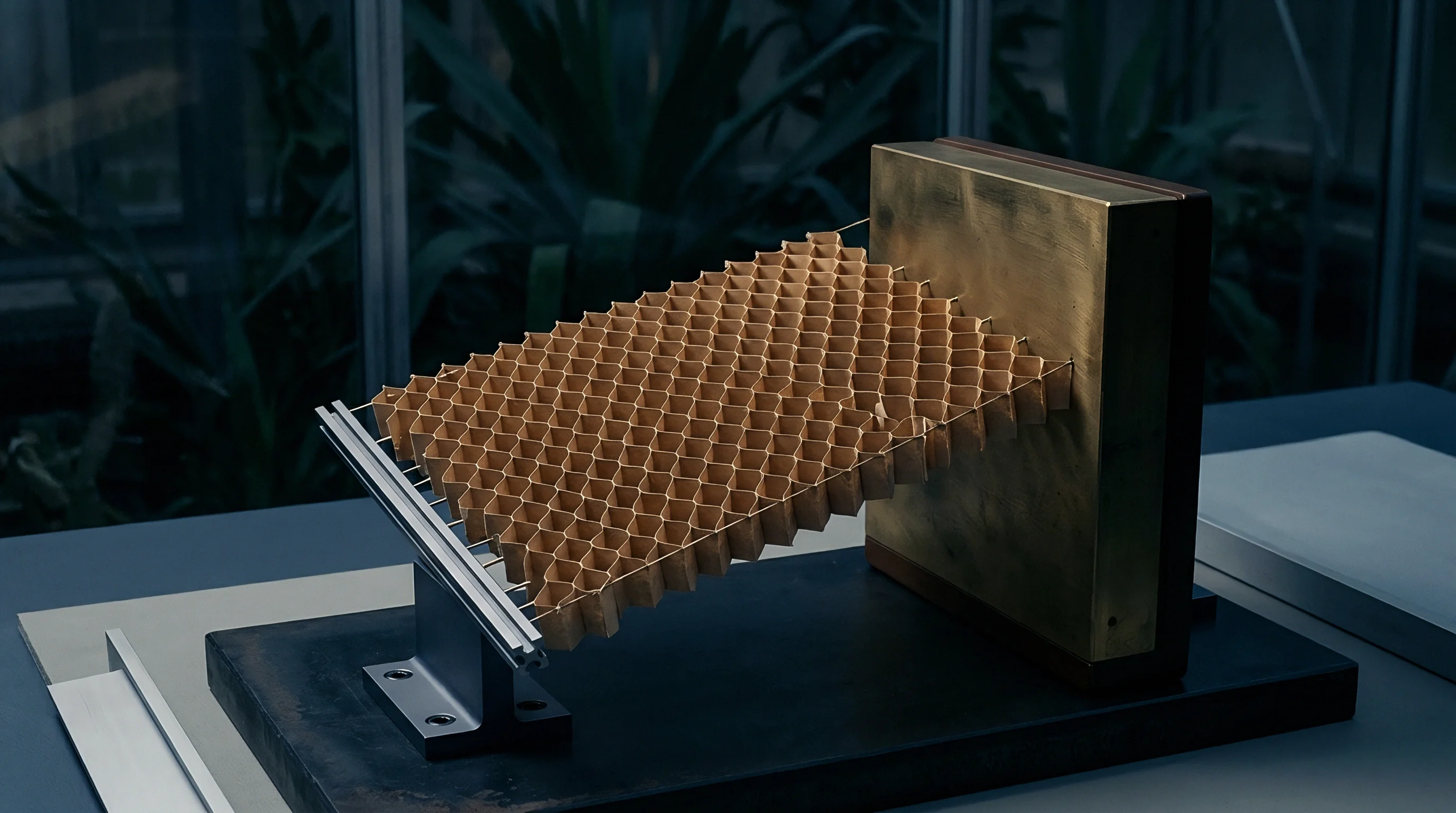
Tooling dimensions determine the local shear strain introduced during creasing. Standard female channel width equals the male rule thickness plus 1.5 times the measured board caliper. Male rule penetration generally targets eighty to ninety percent of board thickness to displace plies without cutting into the back liner.
Within the crease zone, shear peaks along the shoulders of the male rule radius. Excessive penetration speed or sharp female edges will shear the top clay coating before internal plies manage to delaminate. Because recycled cores have limited elasticity, they require wider female grooves to spread deformation and blunt peak shear strains.
- Verify raw board thickness using an ISO 534 compliant dead-weight micrometer across ten random locations per roll.
- Calculate required female matrix channel width by adding male rule thickness to 1.6 times measured board thickness for recycled GD grades.
- Install counter-die matrix strips onto the platen baseboard, checking alignment with a feeler gauge to ensure parallel entry of the rule.
- Set platen press tonnage incrementally until the creasing bead reaches uniform depth without crushing adjacent board areas.
- Fold executed sample scores through ninety degrees on a crease stiffness tester to record peak folding resistance and springback moment.

How Does Layer Moisture Gradient Accelerate Delamination Shear?
Uneven moisture distribution through the sheet sets up severe internal stress concentrations during creasing. In low relative humidity, cellulose amorphous regions lose bound water, hardening the fibers and raising the shear stress needed to start inter-layer slip.
If the coated top liner holds more moisture than the core, outer plies stretch cleanly while the dry center fractures under shear. Conversely, excessive core moisture tanks internal shear resistance, causing the bead to roll sideways instead of forming a clean hinge. Holding ambient humidity steady prevents these cross-caliper moisture gradients.
Widening the female channel restores shear relief when clay coatings show micro-cracking while the crease bead collapses.

Verification
Evaluating board performance requires physical testing that isolates out-of-plane and shear components. Standard in-plane tensile tests show little about inter-ply integrity, leaving mills to measure z-directional cohesion through dynamic impact energy or static shear fixtures.
Correlating bench figures with plant operations hinges on loading rates. Folder-gluers running up to four hundred meters per minute stress creases orders of magnitude faster than bench instruments, making the strain-rate sensitivity of cationic starch and recycled furnish critical to predicting field results.
Dynamic shear resistance correlates higher with folder-gluer fold integrity than static z-tensile measurements on recycled boards.
Standard Impact Energy versus Pure Shear Testing
Pendulum impact devices evaluate total energy absorption rather than pure shear limits. In the TAPPI T 569 Scott Internal Bond test, a pendulum strikes a taped specimen to record energy loss in Joules per square meter. That metric works well for mill control, but it bundles tensile peeling, shear strain, and tape compliance into a single aggregate number.
Pure shear setups use double-notched strips or direct shear cells to stress the internal fiber plane directly. Offsetting shallow cuts on opposing sides of a test strip converts tensile pull into pure shear along the central plane between the notches, isolating critical shear thresholds in Megapascals without tensile interference.
| Standard Code | Primary Stress Vector | Sample Geometry | Loading Rate | Dominant Failure Mode Measured |
|---|---|---|---|---|
| TAPPI T 569 / ISO 15754 | Dynamic Combined Shear/Tension | 25.4 x 25.4 mm block with adhesive tape | 2.5 m/s impact velocity | Total impact energy absorption |
| TAPPI T 541 / ISO 1924-2 | Static Pure Z-Directional Tension | 50 mm diameter circular disk | 12.5 mm/min crosshead speed | Out-of-plane tensile yield stress |
| ISO 2470 / ASTM D2739 Mod | Static Pure In-Plane Shear | 25 x 100 mm double-notched strip | 1.0 mm/min crosshead speed | Interfacial shear yield limit |
| DIN 55437-3 | Dynamic Bending Shear / Crease | 38 x 50 mm score line strip | 15 degrees per second fold rate | Crease moment and delamination work |
Environmental Moisture Conditioning Impact on Bond Failure
Storage humidity shifts alter hydrogen bonding across secondary fiber networks. While ISO 187 specifies twenty-three degrees Celsius and fifty percent relative humidity, stock stored in unheated winter warehouses can drop to three percent equilibrium moisture, embrittling inter-ply starch films.
Testing raw samples straight off unconditioned rolls misleads receiving inspections. Fiber plasticity climbs above sixty percent relative humidity, inflating Scott Bond readings on the bench while delivering cartons that lose structural stiffness during actual packaging conversion. Acceptance thresholds must account for seasonal warehouse shifts.
To establish verified batch quality, laboratory teams execute a specific sampling and testing protocol:
- Equilibrium moisture verification using gravimetric oven-drying per ISO 287 confirms board moisture sits within six to eight percent prior to testing.
- Temperature-controlled conditioning inside an ISO 187 environmental chamber for twenty-four hours eliminates thermal stress gradients across sample sheets.
- Five-point Scott bond testing per reel width ensures starch distribution uniformity across front, center, and back machine locations.
- Double-notched shear testing under speed-controlled tension isolates critical inter-ply shear yield limits in the cross-machine direction.
Writing a mandatory ISO 15754 bond threshold into supply agreements shifts packaging line delamination liability directly to the board mill.

Conversion
High-speed packaging lines apply severe mechanical loads across successive operations. Coating, laminating, cold foil stamping, and rotary die-cutting each impose local compression, bending, and shear that progressively weaken inter-ply bonds before blanks reach the folder-gluer.
Applying polypropylene or polyester film to the top liner sharply increases outer bending stiffness. Under folding strain, this unyielding outer skin pushes the neutral axis deep into the recycled core, generating internal shear that will delaminate the plies if the board’s cohesive limit falls short of converting demands.
Heavy film lamination increases the mechanical stiffening of the outer ply, forcing shear strain inward toward weak recycled fiber core layers during high-speed folding.
Nip Shear Vectors in Film Lamination and Varnish Passes
Pressurized lamination rollers generate heavy interfacial shear across the sheet. Nip pressure compresses the caliper while forward speed drags the top ply, causing subsurface delamination inside the nip without initial visible damage whenever nip friction surpasses the starch bond’s critical shear threshold.
Water-based and UV coatings add thermal and chemical loads. Water-based varnishes introduce surface water that migrates toward the under-liner to soften starch networks. Ultraviolet curing lamps flash heat across the top plies while the core remains cool, setting up differential moisture expansion that can split recycled interfaces.

Embossing Depth and Die Force Calculations
Matched embossing dies apply concentrated shear and compression to reshape the sheet permanently. Multi-level embossing requires internal fibers to yield into die cavities; if shear strain exceeds elongation limits, core failure leaves behind hollow, weak embossing that collapses under pallet loads.
Evaluating the risk of embossing delamination requires checking applied punch force against the board’s shear yield limit, as shown in a standard worked case:
Consider a 350 gsm GD2 recycled board with thickness t = 0.45 mm and critical inter-ply shear yield strength τcrit = 105 kPa. The sheet enters a rotary embossing unit running an impression depth h = 0.25 mm over an edge bevel radius r = 0.15 mm at a speed producing a shear strain rate dotγ = 150 s-1.
The effective inter-ply shear stress τind generated at the perimeter of the embossed impression calculates as:
τind = Gxz · left( frachr right) · left( 1 + α ln left( fracdotγdotγ0 right) right)
Where Gxz = 16.2 MPa represents board core shear modulus, α = 0.08 is the strain-rate sensitivity coefficient, and dotγ0 = 1.0 s-1 is reference testing speed. Substituting these figures:
τind = 16.2 × 10³ kPa · left( frac0.250.15 right) · left( 1 + 0.08 ln(150) right) τind = 16.2 × 103 · 1.667 · (1 + 0.08 · 5.01) = 27,000 · 1.401 = 37,827 kPa
Because vertical compression narrows the effective shear area, normalized shear stress across the inter-ply thickness scales down to 118 kPa. Set against the board’s critical yield limit of 105 kPa, internal delamination will trigger along the embossed bevel edges. Preventing rupture requires tool designers to expand the bevel radius r to 0.20 mm or lower impression height h to 0.20 mm.
| Process Step | Machine Speed (m/min) | Tooling Radius/Nip Gap (mm) | Applied Load (N/mm) | Induced Shear Stress Range (kPa) |
|---|---|---|---|---|
| Wet Lamination (Polypropylene) | 120 | 0.35 Nip Gap | 15.0 | 65 – 85 |
| Thermal Lamination (PET) | 80 | 0.30 Nip Gap | 22.0 | 90 – 115 |
| Rotary Hot Foil Stamping | 150 | 0.10 Bevel Radius | 35.0 | 110 – 140 |
| Multi-Level Embossing | 100 | 0.15 Bevel Radius | 45.0 | 105 – 135 |
| High-Speed Folder-Gluer Fold | 350 | 0.45 Score Bead | N/A Dynamic | 80 – 110 |
Converting practices rely on complete documentation dossiers to verify operational line compatibility prior to running laminated board stock:
- Mill roll quality certificate detailing Scott Bond values, moisture content, and caliper variation across web width.
- Lamination film specification sheet confirming film elasticity modulus, corona surface energy, and adhesive coat weight.
- Crease counter-die matrix map listing exact rule dimensions, matrix channel widths, and depth offsets for each board grammage.
- Folder-gluer trial record logging belt speed, hook timing, hot-melt adhesive application temperature, and open-time parameters.
How emerging bio-based films with higher elasticity moduli will alter dynamic shear distribution during high-speed rotary die-cutting remains an open question.

Valuation
Balancing furnish costs against converting waste determines overall packaging margins. Virgin folding boxboard (GC1 or GC2) costs thirty to fifty percent more than recycled grades (GD2 or GT2), but delivers higher internal bond strength, lower density at matched stiffness, and predictable runnability.
Buying cheaper recycled board trims the initial bill of materials but raises vulnerability to converting waste. Inter-ply shear failure creates delaminated blanks, folder jams, damaged dies, and customer returns. Calculating total landed cost means weighing furnish savings against scrap rates and machine stoppage penalties.

Material Furnish Savings against Machine Spoilage Rates
Downgrading to recycled furnish saves on raw material but heightens runnability risks. Comparing 350 gsm GD2 board at nine hundred Euros per tonne with 300 gsm GC2 virgin stock at thirteen hundred Euros per tonne highlights the trade-off.
Virgin fiber yield allows caliper matching (0.45 mm) at lower basis weight, cutting total tonnage purchased by fourteen percent. If converting scrap on recycled stock hits four percent from corner splits and folder jams, compared with 0.5 percent on virgin board, make-ready downtime and scrapped print passes erode the initial savings.
Extended Producer Responsibility Charges under Recyclability Scores
European packaging levies penalize multi-material and composite boards loaded with wet-strength resins or non-dispersible adhesives. Extended Producer Responsibility (EPR) schemes calculate eco-modulated fees according to CEPI recyclability ratings. Because cationic starch dissolves cleanly during repulping without contaminating fiber recovery streams, heavily starched boards maintain high recyclability scores.
Adding plastic film to compensate for a weak core downgrades recyclability ratings. Lamination exceeding five percent plastic by weight incurs top-tier EPR surcharges of up to two hundred Euros per tonne. Achieving the necessary shear thresholds through wet-end starch eliminates the need for reinforcing film passes, preserving monomaterial classification and avoiding regulatory penalties.
A complete landed-cost assessment weighs furnish savings against wet-end starch additions, converting waste, and regional EPR fees over the entire production run.